
Component Placement in HFSS 3D Layout
Managing complex designs is easier through hierarchical design. A key aspect of hierarchical design is creating and placing component instances with their own unique layer stackup in 3D space within a larger system of components (e.g., placing an HFSS dynamic link or Layout sub-design on a component with an independent layer stackup). Refer to Hierarchical Design.
When a new component is selected in the Layout Editor, the Properties window populates with related parameters, including the 3D Placement check box. When the 3D Placement box is checked, a 3D coordinate manipulator appears in the Layout Editor.
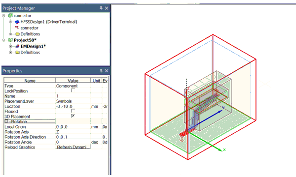
The following properties control the 3D transformation matrix:
- Local Origin – the origin of the 3D Coordinate Manipulator in the component's global coordinate system.
- Rotation Axis – the axis around which the rotation is applied. The rotation axis can be X, Y or Z.
- Rotation Axis Direction – the direction of the rotation axis in the layout's coordinate system.
- Rotation Angle – the rotation angle around the rotation axis.
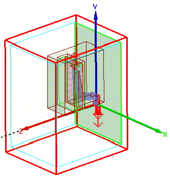
As an example, these properties result in the following component transformation:

- The component is rotated to align the local Rotation Axis (Z) and the Rotation Axis Direction vector is (0, 0, 1).
- A Rotation Angle of 90 degrees is applied to the component about the local Rotation Axis.
HFSS Meshing for Component Instances
Each component instance (i.e., HFSS dynamic link or Layout sub-design) provides an HFSS Mesh property. For HFSS solutions, component instances with this property set to True are integrated into their parent's mesh domain during simulation. Integration allows for accurate simulation of each component's impact on the overall system performance.
Snapping 3D Components in HFSS 3D Layout
After placing a 3D component, you can snap it so that its 3D origin is at the electrical connection point (for pins or vias) or the center, in the absence of an electrical connection point, of the Layout geometry or edge.
- Select a 3D placed component to populate the Footprint tab of the Properties window:

- Select an object (e.g., a pin, primitive, et cetera) or an edge.
- Select Layout > Snap 3D to snap the component to the chosen point.