
Setting up a Near-Field Rectangle
To evaluate near fields on a rectangle, set up a near-field rectangle. Make sure contour plot on sweep of _u and _v can be overlayed in model geometry. Near fields are evaluated on the rectangle centered at the origin of the defined coordinate system of the rectangle with length and width aligned along the X and Y axis of that coordinate system. The plot should have the same size of the rectangle in model units. You can use the near-field rectangle setup to create near-field reports. A near field plot setup in this way can also be overlayed on the geometry and animated.
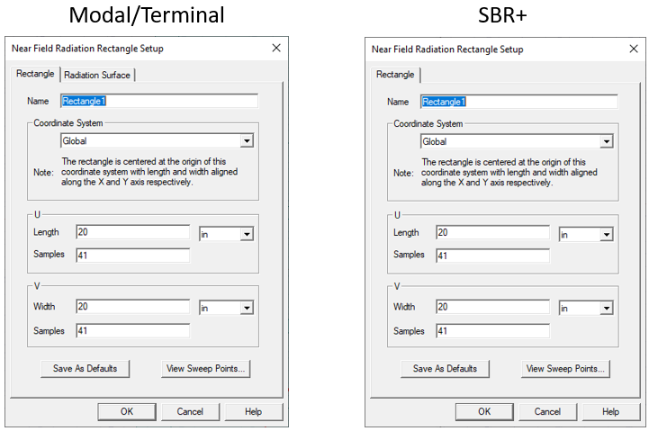
- To create a near-field rectangle setup, click HFSS > Radiation>Insert Near Field Setup>Rectangle to bring up the Near Field Radiation Rectangle Setup dialog. If the design is Modal/Terminal Solution type the dialogue will include a Radiation Surface tab. If the design is HFSS SBR+ or includes SBR+ Hybrid Regions, the dialogue does not include the Radiation Surface tab because with SBR+ designs, the Radiation surface is defined or selected before simulation using the Field Observation Domain pane in the SBR+ Solution setup Options tab or the Hybrid tab of an HFSS Modal or Terminal setup.
- Use the Rectangle
tab define the Name, Relative Coordinate System, and Length, units, number of samples for U and V for the near-field
rectangle. The rectangle is centered at the origin of the coordinate
system you specify. You can assign a variable
to the length and width, and a post-processing
variable will often make sense in this context.
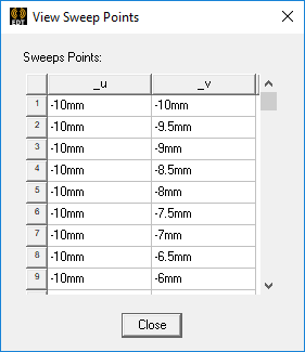
Specify the sphere's sampling as any integer greater than 1. To verify your settings, use the View Sweep Points button to display a list of the U and V sweep points.
You can use Save as Defaults to set the current values as the default for new near-field rectangle setups.
- Use the Coordinate
Systems field and drop down menu to specify the location and orientation of the rectangle. Refer to the Note in the Setup dialog.
The drop down menu consists of the Global CS and all local coordinate systems that you created previously in the modeler
- For a Terminal or Modal design, use the Radiation
Surface tab to select the solved surface from which to calculate
radiated fields.
Use Boundary Radiation Surfaces is selected by default, indicating that the radiated fields will be calculated using the assigned radiation or PML surface. For some models you may find it it more efficient and/or accurate to use an interior surface. In this case, select Use Custom Radiation Surface, and choose a face list that you previously created in the modeler.
You must have defined at least one radiation or PML boundary in the design for HFSS to compute near-field quantities, regardless of which radiation surfaces you instruct HFSS to use when calculating the near fields. You do not need to re-solve the problem if you modify radiation surfaces in the Near Field Radiation Sphere Setup dialog.