
Drawing a Spiral
A spiral is a 2D or 3D spiral object created by sweeping an object around a vector. Sweeping a 1D object results in a 2D sheet object. Sweeping a 2D sheet object results in a 3D solid object. Before you draw a spiral, you can specify the coordinate system, and you can set the drawing plane as Z, Y, or Z, or you can edit the plane in the properties.
- Select the 1D or 2D object you want to sweep to form a spiral.
- From the menu bar, click Draw>
 Spiral or, on the Draw ribbon tab, click the Draw spiral icon:
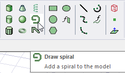
- Draw the vector you want to sweep the object around:
- Select the start point by clicking the point or typing its coordinates in the X, Y, and Z text boxes.
The Status bar also includes options to specify the Coordinate System as Absolute or Relative, and drop down menu options to specify the sphere in Cartesian, Cylindrical, or Spherical coordinates.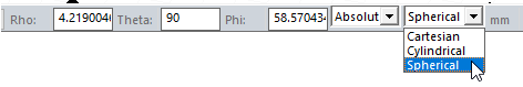
- Select the endpoint by clicking the point or typing its coordinates relative to the start point in the dX, dY, and dZ boxes.
The Spiral dialog box appears.
- Select the start point by clicking the point or typing its coordinates in the X, Y, and Z text boxes.
- Select Right hand if the turn direction is clockwise and Left hand if the turn direction is counter-clockwise.
- In the Radius Change text box, type the difference in radius between each turn of the spiral.
The radius of the first turn is measured from the center point of the 1D or 2D object you are sweeping to the vector you drew.
- Click a unit for the radius in the pull-down list.
- In the Turns text box, type the number of complete revolutions the object will make around the vector.
The selected object is swept around the vector to form a spiral. The original object you swept is deleted. If the Modeler option for editing properties of new primitives is checked, the Properties dialog box appears, enabling you to modify the object's properties.
- Click OK.
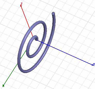
This 3D spiral was created from a 2D circle drawn at z = 0. The turn direction was right hand, the radius change was set at 2, and the number of turns was set at 2.
The 3D Modeler permits drawing true curved objects. However, the solution is obtained using a tetrahedral mesh, which conforms to the true surface only within the limits identified by certain mesh settings. The modeler has default settings for this conformance, which is a reasonable trade-off between solution speed and solution quality for most objects but may not be ideal for all such objects. High-aspect ratio curves structures (such as helices with narrow and curved cross-sections) may benefit from user control of the faceting values. For details about these commands see:
Rectilinear Elements and Curvilinear Elements and Guidelines for Modifying Surface Approximations.