Drawing a Rectangle
Draw a rectangle (or square) by selecting two diagonally opposite corners. Before you draw a rectangle, you can specify the coordinate system, and you can set the drawing plane as Z, Y, or Z, or you can edit the plane in the properties.
- From the menu bar, click Draw>
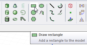
 Rectangle or, on the Draw ribbon tab, click the Draw rectangle icon:
- Select the first diagonal corner in one of the following ways:
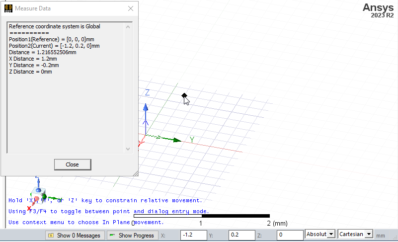
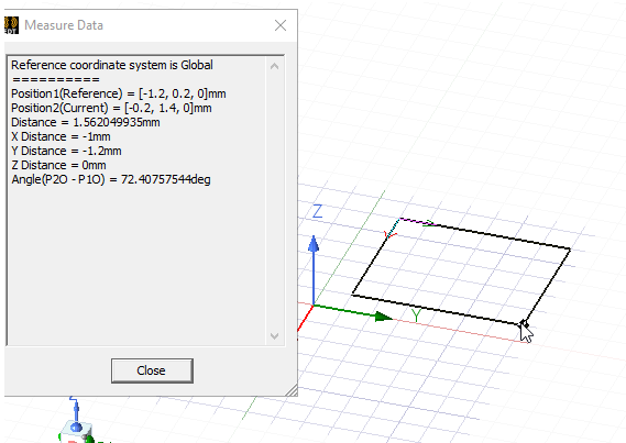
- Click the point. The Measure Data dialog shows the coordinates and other information.
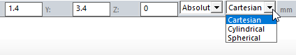
- Type the point's coordinates in the text boxes in the status bar. The Status bar also includes options to specify the Coordinate System as Absolute or Relative, and drop down menu options to specify the cylinder in Cartesian, Cylindrical, or Spherical coordinates.
To delete the selected point and start over, press Esc or click Escape Draw Mode on the shortcut menu.
- Click the point. The Measure Data dialog shows the coordinates and other information.
- Select the second corner of the rectangle in one of the following ways:
- Click the point.
- Type the coordinates of the point relative to the first diagonal corner in the dX, dY, and dZ boxes, where d is the distance from the previously selected point.
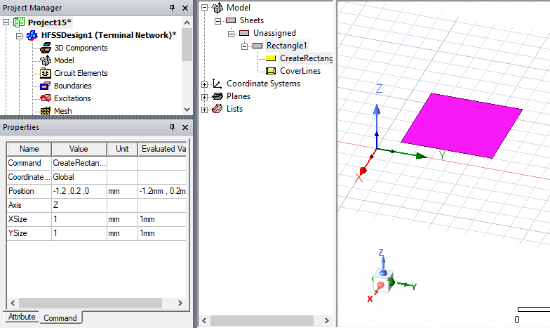
If the Modeler option for editing properties of new primitives is checked, the Properties dialog box appears, enabling you to modify the object's properties. You can also use the docked Properties window.
- Click the point.
- Click OK.