
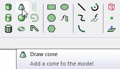
Drawing a Cone
Draw a cone by selecting the center point and radius of the cone's base circle, then specifying the radius of the cone's top circle and the cone's height. Cones are drawn as true surfaces in the modeler. Before you draw a cone, you can specify the coordinate system, and you can set the drawing plane as Z, Y, or Z, or you can edit the plane in the properties.
- From the menu bar, click Draw>
 Cone or, on the Draw ribbon tab, click the Draw cone icon:
- Select the center point of the cone's base circle in one of the following ways:
- Click the point.
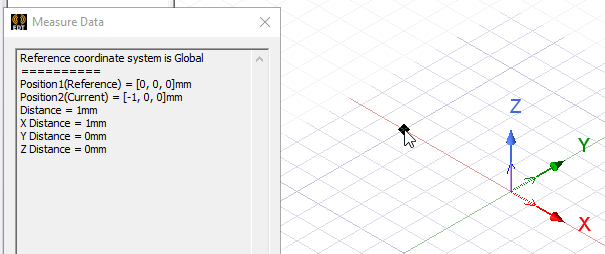
- Type the point's coordinates in the text boxes in the status bar.

The Status bar also includes options to specify the Coordinate System as Absolute or Relative, and drop down menu options to specify the cone in Cartesian, Cylindrical, or Spherical coordinates.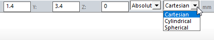
- Click the point.
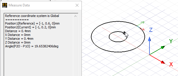
- Specify the radius of the cone's base circle by selecting a point on the base circle's circumference. Select the point in one of the following ways:
- Click the point.
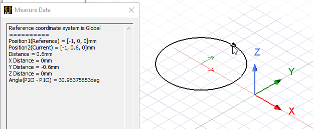
- Type the coordinates of the point relative to the center point in the dX, dY, and dZ boxes, where d is the distance from the previously selected point.
- Click the point.
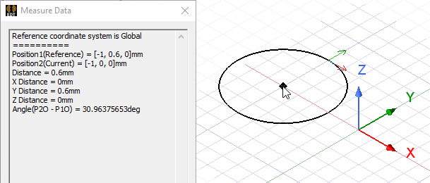
- Specify the radius of the cone's top circle by selecting a point on its circumference. Select the point by clicking it or typing its coordinates in the dX, dY, and dZ boxes.
To create an apex, select the same center point as the cone's base circle.
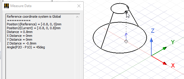
- Specify the height of the cone by selecting a point on the axis perpendicular to the base circle's plane. Select the point by clicking the point or typing the coordinates in the dX, dY, and dZ boxes.
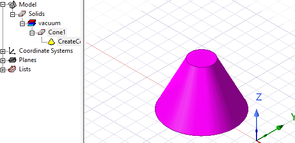
- Double click, or right click and select Done from the short cut menu. If the Modeler option for editing properties of new primitives is checked, the Properties dialog box appears, enabling you to modify the object's properties. The cone appears in the Modeler window and in the History Tree.
The 3D Modeler permits drawing true curved objects. However, the solution is obtained using a tetrahedral mesh, which conforms to the true surface only within the limits identified by certain mesh settings. The modeler has default settings for this conformance, which is a reasonable trade-off between solution speed and solution quality for most objects but may not be ideal for all such objects. High-aspect ratio curves structures (such as helices with narrow and curved cross-sections) may benefit from user control of the faceting values. For details about these commands see:
Rectilinear Elements and Curvilinear Elements and Guidelines for Modifying Surface Approximations.