Creating Circuit Ports in IC Mode
Circuit ports can be created the same way in both General and IC Modes. Refer to the HFSS 3D Layout Creating a Circuit Port page for further information.
Creating a Point-to-Point Circuit Port
Complete these steps to create a circuit port.
-
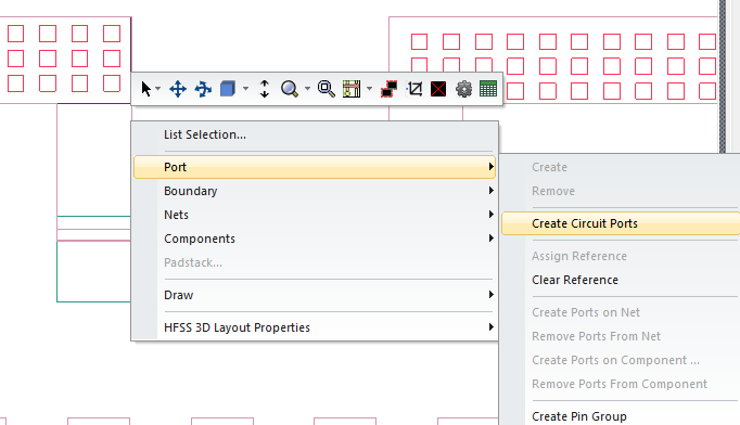
Right-click within the Layout Editor and select Port > Create Circuit Ports.
-
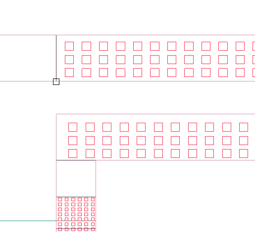
Hover the cursor over a conductor until the cursor changes shape (i.e., from an arrow into a square). Then left-click the conductor to select it as the positive terminal.
-
Repeat step 2, now dragging the port behind the cursor. Hover the cursor over a conductor until the cursor changes shape, then left-click the conductor to set it as the negative terminal.
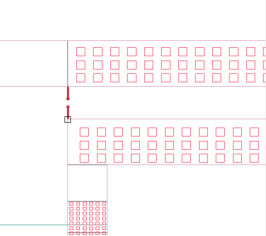
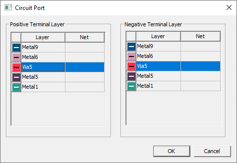
The Circuit Port window will open.
-
From the Circuit Port window, select a Positive Terminal Layer and a Negative Terminal Layer.
-
Click OK to close the Circuit Port window and finalize the new circuit port.
Editing Circuit Ports
Complete these steps to edit a circuit port's properties.
-
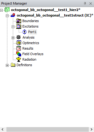
Navigate to the Project Manager window. Then expand the Project Tree > [Active Design Folder] > Excitations folder.
-
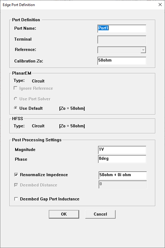
Double-click the chosen port (e.g., Port1) to open the Edge Port Definition window.
-
From the Edge Port Definition window, users can perform the following tasks:
- Change the name of the pad port.
- De-embed the S-matrices.
- Vary the port excitation.
- Renormalize the port to a specific port impedance.
- Set up a reference to the nearest negative signal.
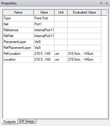
When a circuit port is selected, its parameters appear in the Properties window. Some values, such as the port's positive and negative terminal layers, can be changed directly in the Properties window.
