
Creating a Circuit Port
Circuit ports can be created in multiple ways: automatically referenced to the closest ground plane, between two edges, or point-to-point. All circuit ports are listed under Excitations in the Project Tree. To edit a circuit port’s properties, double-click the port in the Project Tree to open the Edge Port Definition window.

To create a circuit port automatically referenced to the closest ground plane, select an edge of a conductor, right-click and select Port > Create Circuit Ports on the floating menu.
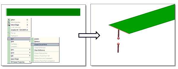
A circuit port are created with the selected edge as its positive terminal and the nearest ground plane as its negative terminal.
To create a circuit port between two edges, select a pair of edges from different conductors, right-click and select Port > Create Circuit Ports on the floating menu.
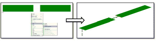
The first selected edge defines the positive terminal and the second selected edge defines the negative terminal of the port.
Circuit ports can also be introduced in a point-to-point manner. With no edges selected, right-click and select Port > Create Circuit Ports on the floating menu.
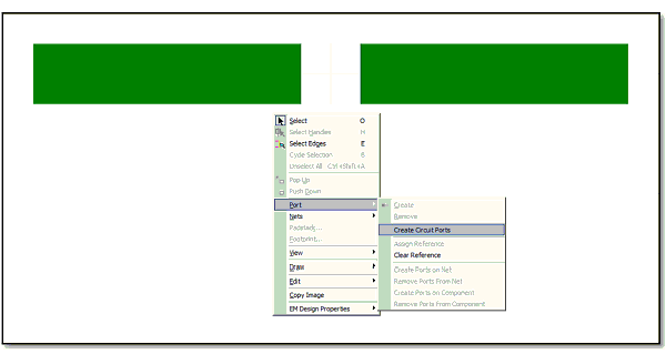
Click on a conductor to select the positive terminal.

Click on a second conductor to select the negative terminal.

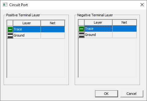
A window appears that allows the selection of a layer for each terminal.
The circuit port is listed under Excitations in the Project Tree. To edit the port’s properties, double-click the edge port in the Project Tree. The Edge Port Definition window opens where you can perform these tasks:
- Change the name of the pad port.
- De-embedding S-Matrices.
- Vary the current excitation.
- Renormalize the port to a specific port impedance.
- Setup a Reference to the Nearest Negative Signal.
When the circuit port is selected, its EM Design tab is available in the Properties window. This tab displays many of the values in the Edge Port Definition window, the Planar EM Solution, and port classification for the HFSS-PI type. The Footprint tab lists whether the circuit port is a point or edge port.
A port can be split across multiple signal layers. It can be made of up to three different line segments on three different primitive objects. Ports located over apertures in negative signal planes can generate incorrect results. HFSS automatically displays a warning message if referencing a gap source to the nearest negative signal produces such an error.