Adding a RaptorX Solution Setup in IC Mode
RaptorX is a pre-LVS electromagnetic (EM) modeling solver created especially for integrated circuit designs.
Setting Up a RaptorX Simulation
Complete these steps to add a RaptorX solution setup to a project in IC mode.
- Open the RaptorX Solution Setup window by doing one of the following:
- From the Project Manager window, expand the Project Tree > [Active Design Folder] (e.g., spiral_ind_single > EMDesign1). Then right-click Analysis and select Add RaptorX Solution Setup.
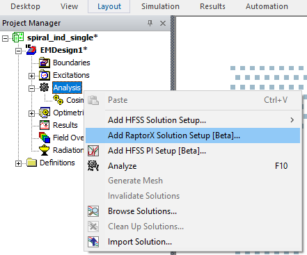
- From HFSS 3D Layout, select Solution Setup > RaptorX > Add RaptorX Solution Setup.

- From the Project Manager window, expand the Project Tree > [Active Design Folder] (e.g., spiral_ind_single > EMDesign1). Then right-click Analysis and select Add RaptorX Solution Setup.
-
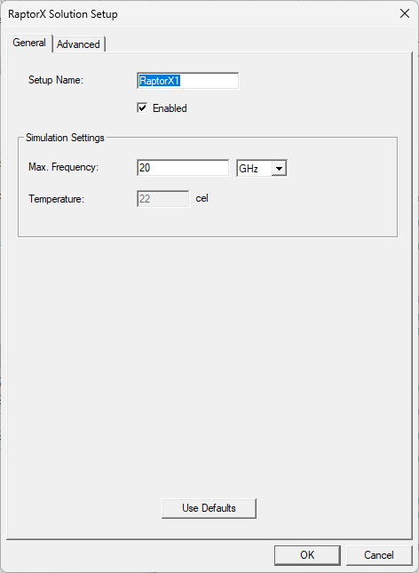
From the RaptorX Solution Setup window, make selections from the General and Advanced tabs. Default values shown.
-
From the General tab, set the following:
-
Setup Name – enter a name in the field or accept the default.
-
Enabled – check the box to activate the setup.
-
Max. Frequency – enter a value in the adjacent field to specify the maximum simulation frequency (Ansys recommends at least 10 GHz) and select a unit of measurement from the corresponding drop-down menu.
-
Temperature – specifies the simulation temperature. To modify the simulation temperature, refer to Setting Uniform Temperature in HFSS 3D Layout.
-
- Click the Advanced tab.

-
From the Advanced tab, check the corresponding box adjacent to any or all of the following settings to activate them. Then enter any appropriate value(s) and/or make drop-down menu selections, as applicable.
-
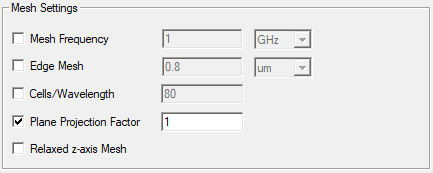
From the Mesh Settings area, set the following:
-
Mesh Frequency – enter a value in the adjacent field to specify a custom frequency for mesh generation. Then select a unit of measurement from the corresponding drop-down menu. A higher mesh frequency improves simulation accuracy.
-
Edge Mesh – enter a value in the adjacent field to specify the thickness and width of the exterior conductor filament. Then select a unit of measurement from the corresponding drop-down menu. Edge Mesh prevails over Max. Frequency and Mesh Frequency. If Edge Mesh is left unchecked, edge mesh is calculated internally equal to the layer depth defined by Mesh Frequency or Max. Frequency.
-
Cells/Wavelength – enter a value in the adjacent field to specify the number of cells under each wavelength. Wavelength is calculated according to Max. Frequency or Mesh Frequency (e.g., If users enter 20 in the Cells/Wavelength field, the design is divided into 10 cells if its width or length is 1/2 wavelengths).
-
Plane Projection Factor – enter a value in the adjacent field to set a hard limit on the complexity of the simulation. The mesh conforms to the limit to improve extraction time. Activate Plane Projection Factor, then refer to Changing Net Settings to set individual values for certain nets.
-
Relaxed z-axis Mesh – check the box to simplify mesh along the z-axis. If the thickness of a conductor is greater than three times the layer depth, then instead of performing dynamic meshing, Relaxed z-axis Mesh creates no more than three filaments along the z-axis. The top and bottom filament thickness are equal to layer depth, as previously calculated, and the middle filament is equal to the remaining thickness. This improves extraction time and resource use with a negligible effect on accuracy.
-
-
From the Geometry Specification area, set the following:

-
Eliminate Slit/Holes – enter a value (i.e., threshold) to simplify designs with strain relief or thermal relief slits and/or holes. Any slits/holes below the threshold are filled.
-
Automatic Removal of Sliver Polygons – enter a value threshold to simplify layouts by aligning slightly misaligned polygons. Any overlap below the threshold is removed.
-
Accelerate Via Extraction – check the box to merge neighboring vias. Merged vias are treated as ideal (i.e., non-resistive).
-
-
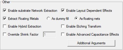
From the Other area, set the following:
-
Enable substrate Network Extraction – models substrate coupling effects by simulating an equivalent distributed RC network. Checked by default.
-
Enable Layout Dependent Effects – calculates the variation of resistivity as a function of a conductor's drawn width and spacing to its neighbors or as a function of its local density, due to dishing, slotting, cladding thickness, et cetera. Checked by default.
-
Extract Floating Metals – after activating, select either of the following:
-
As dummy fill – calculates the effective capacitance between any pairs of metal segments in the design, while taking into account the presence of dummy metal islands that are not included in a net. This fill is represented as a new entity (i.e., dummyFill). Mesh Frequency does not apply to dummyFill.
-
As floating nets – groups every metal segment in the design not explicitly included in a net in a new entity (i.e., floatingNets), which will be meshed according to Mesh Frequency settings.
-
-
Enable Hybrid Extraction – assumes electromagnetic (EM) effects dominate the top (metal) layers of the design, so the design is separated horizontally into two parts. The upper part is assumed to contain a smaller number of ports compared to the bottom, potentially decreasing extraction time significantly.
-
Override Shrink Factor – enter a value to override the default shrink factor.
-
Enable Etching Transform – distorts the design based on foundry rules and applies the conductor's bias (i.e., positive/negative, deflation/inflation) at the conductor's edges due to presumed unavoidable effects in the manufacturing process. Ignored if LDE data is not present.
-
Enable Advanced Capacitance Effects – applies capacitance-related effects to the design (e.g., conformal dielectrics, loading effects, and/or dielectric damage).
-
Additional Arguments – click to open the Additional Extraction Arguments window.
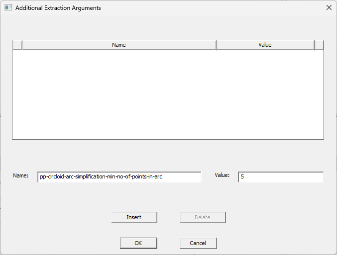
From the Additional Extraction Arguments window, do the following:
-
Enter one or more arguments from the following list in the Name field. Then enter an appropriate Value.
Argument Name Value edt-validate-afet-simplify-dielectrics - 0 (Default) – Dielectrics are not simplified while running the RaptorX simulation.
- 1 – Dielectrics are simplified while running the RaptorX simulation.
Note: If False, then pp-circloid-arc-simplification-try-octagons (if inserted) must have the value True.pe-edt-name-based-sub-backplane - 0 – During simulation, substrates and backplanes are automatically detected.
- 1 – Layers named backplane or ground are modeled as backplanes. Layers named substrate or sub are modeled as substrates.
Note: If 1, naming conventions are spelling and case-sensitive (i.e., backplane, not Backplane; ground, not grnd).pe-edt-package-vias Comma-separated list of via layers, which will be designated as package vias (e.g., via1, via2, et cetera). Note: This parameter is ignored if a technology definition is applied to the design.pp-circloid-arc-simplification-min-no-of-points-in-arc The minimum number of points in a circloid arc. Default value is 5. pp-circloid-arc-simplification-try-hexadecagons - True (Default) – Use hexadecagons for circloid-arc simplification.
- False – Do not use hexadecagons for circloid-arc simplification.
Note: If False, then pp-circloid-arc-simplification-try-octagons (if inserted) must have the value True.pp-circloid-arc-simplification-try-octagons - True – Use octagons for circloid-arc simplification.
- False (Default) – Do not use octagons for circloid-arc simplification.
Note: If False, then pp-circloid-arc-simplification-try-hexadecagons (if inserted) must have the value True.pp-via-stacking - True (Default) – A stacking approach is used on silicon vias, merging any overlapping vias in adjacent layers into a single stacked region.
- False – A stacking approach is not used on silicon vias.
vr-extract-c Enter 0 to skip capacitance calculation.
-
Click Insert to save the argument.
-
Repeat steps a-b, as appropriate.
Note:Internal operations can be overridden using additional arguments (i.e., create the argument vr-extract-c with a value of 0 to skip capacitance calculation).
-
Then click OK to close the window and return to the RaptorX Solution Setup window.
-
-
-
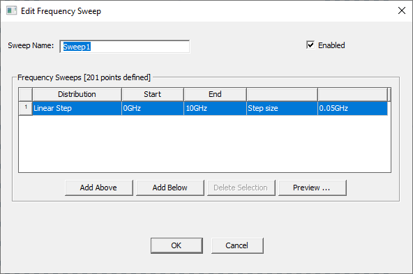
- Click OK to add the RaptorX solution setup to the active design and simultaneously open the Edit Frequency Sweep window.
-
From the Edit Frequency Sweep window, click OK to accept the sweep with its default values or change the default values before continuing. Refer to Adding a Frequency Sweep for more information.
Changing Net Settings
RaptorX solution setups can be customized further by making changes to the Mesh Frequency and Edge Mesh parameters for specific nets. Complete these steps to view all of the nets recognized by RaptorX during simulation, including the virtual nets created as a result of user-selected options chosen during setup (e.g., such as the floatingNets group created by activating Extract Floating Metals), and modify as appropriate.
-
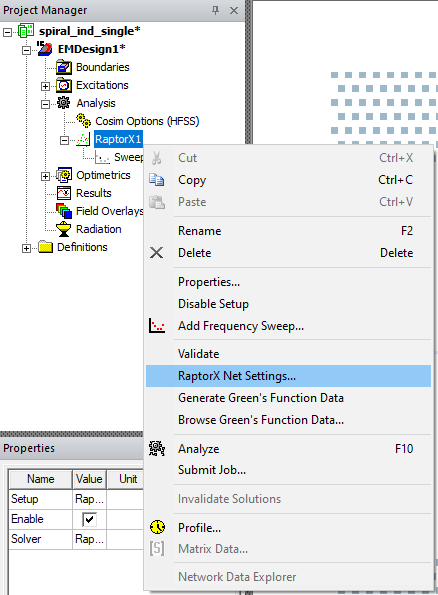
From the Project Manager window, expand Analysis. Then right-click the RaptorX solution setup (e.g., RaptorX1) and select RaptorX Net Settings to open the RaptorX Net Settings window.
-
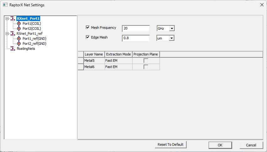
From the RaptorX Net Settings window, select a mesh to view its individual settings or Ctrl+click/Shift+click to select multiple meshes.
-
Check the corresponding box adjacent to any or all of the following settings to activate them. Then enter any appropriate value or make drop-down menu selections, as applicable. The settings function as described in Setting Up a RaptorX Simulation.
-
Mesh Frequency
-
Edge Mesh
-
Projection Plane (active if Plane Projection Factor is also active in the RaptorX Solution Setup window)
-
-
Click OK to close the RaptorX Net Settings window.
Applying Technology Definition Files
If any technology definition files were imported during the initial setup of the design, complete these steps to apply a technology definition before simulation.
If technology definitions were not imported during the initial setup of the design, users can add one or more files at any time before simulation. If a technology definition was applied during setup, the definition's name should already appear in the Layout ribbon adjacent to the Technology drop-down menu. Users will not need to complete these steps. Refer to Adding a Technology Definition File to a Design.
-
If a technology definition is available, navigate to the Layout ribbon and select Apply Technology from the Technology drop-down menu.

-
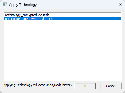
Once the Apply Technology window opens, select an appropriate technology definition file from the list and click OK.
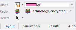
Once the technology definition is applied to the design, the definition's name appears adjacent to the Technology drop-down menu.
Analyzing the Design and Post-Processing
Complete these steps to analyze the new RaptorX solution setup, then create an overlay, mesh, and generate a report.
-
From the Project Manager window, right-click RaptorX1 and select Analyze to run the simulation. Refer to Running Simulations.
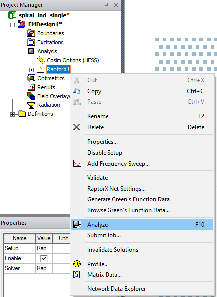
If this is the first time the design has been analyzed with a RaptorX solution setup, Green's Function Data is generated during the analysis.

-
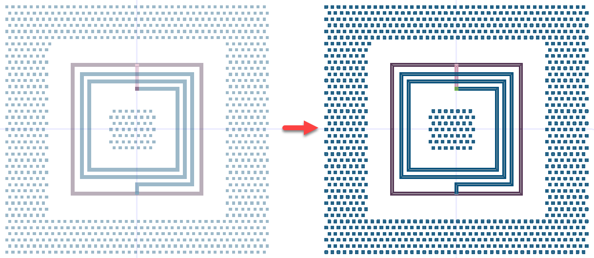
Once the simulation is complete, a mesh visualization is generated. Navigate to the Project Manager window and expand RaptorX1. Then right-click Sweep1 and select Results > Display Mesh.
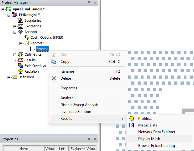
The mesh visualization overlay immediately appears on the design.
-
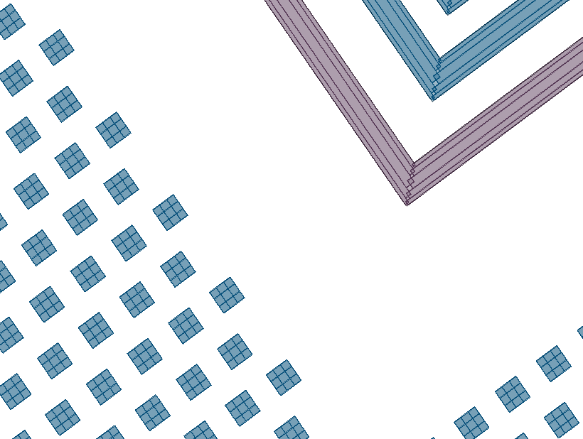
Reorient the design to view the mesh visualization from different angles.
-
From the Layers window, control which layers of the mesh visualization are visible.
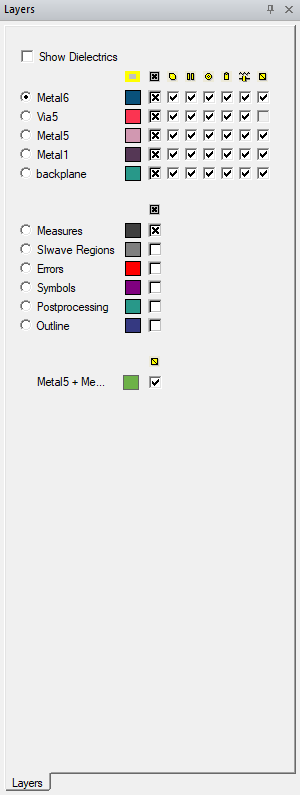
Add or remove checks from the right-hand column (i.e., the Mesh column) to show or hide layers of the mesh visualization.

The lowest quadrant of the Layers window displays mesh groups created by RaptorX. Refer to Viewing Green's Function Data.

The procedure is complete.
