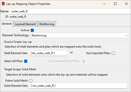
The figure below shows the settings for a Layup Mapping Object that includes reinforcing elements. Set Element technology to Reinforcing to ensure that reinforcing layers are handled correctly. Use the source and target scopes to select the plies and map them to the appropriate solid‑element set.
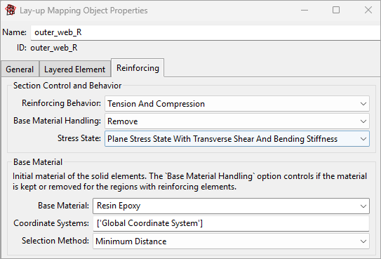
The Reinforcing tab controls the section behavior, stress state, and base material for the reinforcing plies (see Figure 4.77: Reinforcing Tab of the Layup Mapping Object). The default settings are used in this example.
Reinforcing plies can carry tension and compression loads. Their full 3D stiffness— including in‑plane, out‑of‑plane shear, and bending— is added to the underlying solid mesh. In addition, the solid material is removed wherever it intersects with the reinforcing plies.
The base material is resin, which defines the default material for solid elements that do not intersect with reinforcing layers.
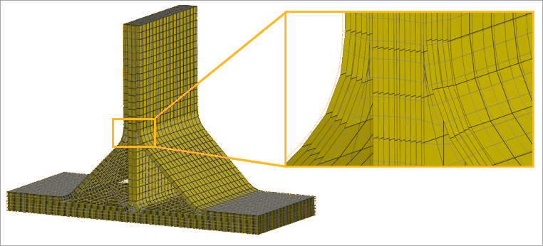
You can visualize the reinforcing plies in ACP by selecting the analysis plies of either the Imported Solid Model or the Layup Mapping Object. The reinforcing surfaces of the T‑joint are shown in Figure 4.77: Reinforcing Tab of the Layup Mapping Object and help verify that the configuration is correct.