


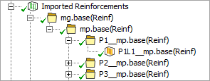
When the downstream Mechanical system updates, reinforcing plies appear under Imported Reinforcements. You can verify the mesh directions, material assignments, and ply angles as shown in Figure 4.79: Imported Reinforcements Properties.
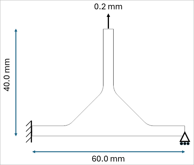
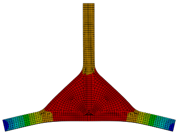
The boundary conditions and dimensions are shown in Figure 4.80: T-Joint Boundary Conditions and Dimensions. The T‑joint is fixed on the left side, enabling rotation of the cross-section. A simple support is applied on the right side, and a vertical displacement is applied to the top face. The total laminate thickness is 4 mm.
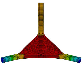
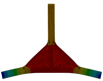
The deformation results and reaction forces from all three analyses are summarized in the table below. The reaction forces are similar across the models. The layered solid model is used as the reference.
| Reinf + Quad Mesh | Reinf + Tet Mesh | Layered Solid | |
| System | E | I | G |
| U sum |
 |
 |
 |
| Reaction force [N] | 835.87 | 834.37 | 848.32 |
| Error [%] | -1.47 | -1.64 | 0 (reference value) |