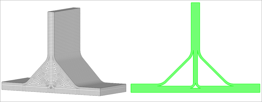
The T‑joint solid mesh is created in the Mechanical application and transferred to ACP using the Imported Solid Model feature. The T‑joint consists of three primary components:
Layered composite parts (see Figure 4.73: Base Mesh and Layered Composite Part)
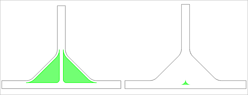
Foam inserts (see Figure 4.74: Foam Inserts (Left) and Resin Pocket (Right))
Resin pocket (see Figure 4.74: Foam Inserts (Left) and Resin Pocket (Right))
ACP uses multiple reference surfaces to define plies for each reinforced region of the T-joint. These plies function as the reinforcing surfaces in the layup model.
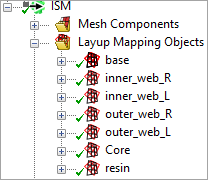
ACP links the layup to the solid mesh through the Imported Solid Model feature. In this workflow, Layup Mapping Objects map each ply to the target solid‑element sets. Because each mapping object can be scoped to individual solid components, you can assign different configurations to each structural region of the T‑joint.
The T‑joint uses the following mapping objects (see Figure 4.75: Layup Mapping Objects):
Layered carbon fiber reinforced parts: base, inner_*, outer_*
Foam inserts: core
Resin pocket: resin
Foam and resin regions are modeled as homogeneous. Their layup mapping objects only assign the base material and element orientations.