


The following options specify how probe annotation labels are displayed:
For additional display options that can apply to probe annotation labels, see Graphics Annotation Window Features
Displaying Node IDs/Element IDs in Probe Annotations
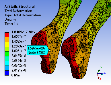
The probe annotation label displays the solution value and (optionally) the node ID at the label's anchor point. If Snap is active, probe annotation labels automatically anchor to the nearest node ID or element ID. This feature is controlled by the Show Mesh Entity ID in Snap-Probe Labels preference, which is available in the Options dialog under the Graphics settings in the Interactive and Min/Max Probes category category.
Show Mesh Entity ID in Snap-Probe Labels is set to Yes by default. To remove the node ID or element ID from the probe annotation label, set it to No.
|
Probe Label
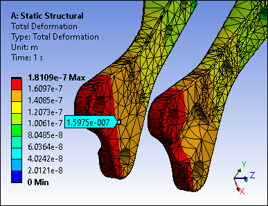
|
Probe Label with Node ID
|
Displaying Node IDs/Element IDs and Results Values in Minimum and Maximum Annotations
To display the node ID or element ID and the results value on the Max and Max annotation labels, set Show Detailed Information in Min/Max Probe Labels to Yes. This preference is available in the Options dialog under the Graphics settings in the Interactive and Min/Max Probes category category. It is set to No by default.
Moving Probe Annotations
Probe annotation labels can be moved anywhere within the Geometry window. Use your mouse to drag-and-drop the label to a different location. As shown below, a white line directs you to the label's anchor point on the model. In addition, two vertical red lines appear beside a label when it is moved.

The anchor of a probe annotation label always remains in its original position. To return the label to its original position, click it in the Geometry window to select it and press the Esc key. Hold down the Ctrl key to select multiple labels.
A probe annotation label remains stationary after it is moved. If you rotate or move the model, the label remains in the same position in the window. As needed, you can simply return the annotation to its original location or drag-and-drop it to a new location to reposition it along with the model.
Probe Annotation Display Font
When the Probe option is selected in the Results context menu and you move the cursor over your model, result values display. You can change the default display settings for the font using the Probe Tool and Hit Point Coordinate preference under the Graphics category in the Options dialog. This preference enables you to change the attributes (font, size, style, color) of the font. The following figure shows results in white Calibri Bold, Size 18.

Probe Annotation Flexibility and Scaling
Probe annotation labels can be “flexible” and move with the deformed mesh whenever you make a change to the Deformation Scale Factor, as illustrated below. This behavior is controlled by the preference under the Graphics category in the Options dialog.
By default, this preference is set to Yes. If it is set to No, the application deletes probe labels whenever you make a change to the scale factor.


Limitation: The application cannot flex a probe's anchor location using the Geometry menu display options , , or . If you place a probe annotation label when any of these options are active and then change the scaling, the application automatically removes/deletes the probe labels.
Probe Annotation Line Coloring
To change the color of the line connecting the probe annotation label to its anchor point, use the Probe Line Color property in the Graphics category of the Options dialog.
