


As shown in the figure below, the error tolerance, numerical damping, step size, and various other parameters for the simulation can be defined in the Thermal tab of simulation configuration dialog. The parameters are described in the table below.
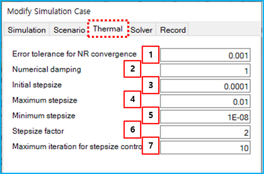
Figure 9.40: Thermal parameters in the simulation configuration
| Feature | Description | Dimension (Range) |
| 1. Error tolerance… | Use to set the error tolerance to check a convergence of nonlinear equation solver. For more information, see Dynamic Parameters for Simulation Configuration. |
N/A (Real>0.0) |
| 2. Numerical damping | Use to set the numerical damping. For more information, see Dynamic Parameters for Simulation Configuration. |
N/A (0≤Real<4) |
| 3. Initial step size | Use to set an initial integration step size. For more information, see Dynamic Parameters for Simulation Configuration. |
Time (Real>0.0) |
| 4. Maximum step size | Use to set the maximum integration step size. For more information, see Dynamic Parameters for Simulation Configuration. |
Time (Real>0.0) |
| 5. Minimum step size | Use to set the minimum integration step size. For more information, Dynamic Parameters for Simulation Configuration. |
Time (Real>0.0) |
| 6. Stepsize factor | Use to set a factor for increasing and decreasing integration step size. For more information, see Dynamic Parameters for Simulation Configuration. |
N/A (Real≥1.0) |
| 7. Maximum iteration… control | Use to set a maximum integration step under same integration step size. For more information, see Dynamic Parameters for Simulation Configuration. |
N/A (Integer>0) |