


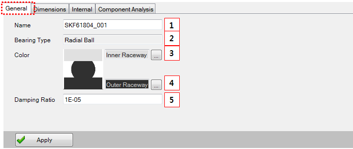
Figure 14.232: Parameters in the Deep groove ball bearing General tab
| Parameter | Description |
Dimension (Range) |
| 1. Name | Use to set the bearing name. | N/A |
| 2. Bearing Type | Bearing type (read only) | N/A |
| 3. Color(inner) | Select the color of the inner raceway. | N/A |
| 4. Color(outer) |
Select the color of the outer raceway. This is also applied to ball color. | N/A |
| 5. Damping ratio | Use to set the damping ratio. | N/A |
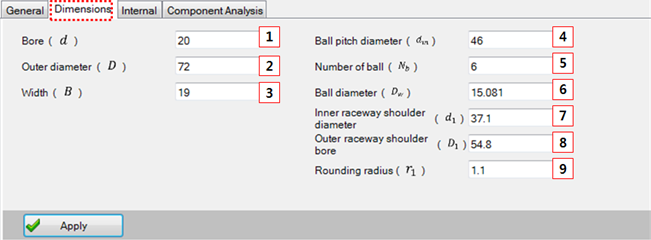
Figure 14.234: Parameters in the Rolling bearing Dimensions tab
| Parameter | Description |
Dimension (Range) |
| 1. Bore | Use to set the bore. | Length (mm) |
| 2. Outer diameter | Use to set the outer diameter. | Length (mm) |
| 3. Width | Use to set the width. | Length (mm) |
| 4. Ball pitch diameter | Use to set the ball pitch diameter. | Length (mm) |
| 5. Number of ball | Use to set the number of balls. | N/A |
| 6. Ball diameter | Use to set the ball diameter. | Length (mm) |
| 7. Inner raceway shoulder diameter | Use to set the shoulder diameter the of inner raceway. | Length (mm) |
| 8. Outer raceway shoulder bore | Use to set the shoulder diameter of the outer raceway. | Length (mm) |
| 9. Rounding radius | Use to set the rounding radius. | Length (mm) |
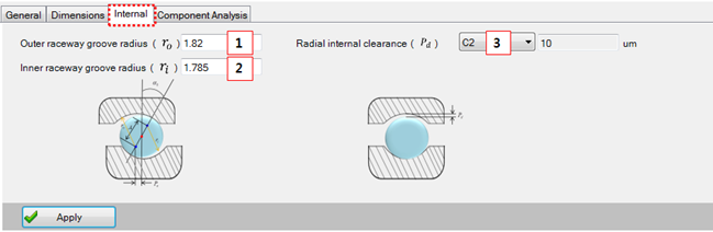
Figure 14.236: Parameters in the Deep groove ball bearing Internal tab
| Parameter | Description |
Dimension (Range) |
| 1. Outer raceway groove radius | Use to set the groove radius of the outer raceway. | Length (mm) |
| 2. Inner raceway groove radius | Use to set the groove radius of the inner raceway. | Length (mm) |
| 3. Radial internal clearance | Use to set the radial clearance. | Length (um) |
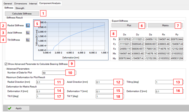
Figure 14.238: Parameters in Component Analysis tab - Stiffness of Deep groove ball bearing
| Parameter | Description |
Dimension (Range) |
| 1. Calculate Stiffness | Use to run the stiffness calculation. | N/A |
| 2. Radial Stiffness | Show the radial stiffness graph on plot window. | N/A |
| 3. Axial stiffness | Show the axial stiffness graph on plot window. | N/A |
| 4. Tilt stiffness | Show the tilt stiffness graph on plot window | N/A |
| 5. Plot Window | Show the deformation-stiffness graph | N/A |
| 6. Export Plot | Use to export the plot result. This will create a file including the radial, axial, and tilt stiffness results. | N/A |
| 7. Export Matrix | Use to export the matrix result. This will create a file including the matrix result. | N/A |
| 8. Matrix Result | Show the bearing stiffness matrix. |
N/mm Or Nmm/deg |
| 9. Show Advanced… | Use to set whether you want to set advanced parameters. If selected, you can modify the parameters to calculate stiffness and when you click the calculate stiffness button again, the program will use these parameters. | N/A |
| 10. Number of Data | Use to set the number of data to calculate the stiffness plot result. | EA |
| 11. Maximum Deformation for Radial Direction | Use to set the maximum deformation for radial direction to calculate the radial stiffness plot result. | mm |
| 12. Maximum Deformation for Axial Direction | Use to set the maximum deformation for axial direction to calculate the axial stiffness plot result. | mm |
| 13. Maximum Deformation for Tilt | Use to set the maximum deformation for tilt to calculate the tilt stiffness result. | deg |
| 14. Deformation X (mm) | Use to set the deformation x to calculate the stiffness matrix result. | mm |
| 15. Deformation Y (mm) | Use to set the deformation y to calculate the stiffness matrix result. | mm |
| 16. Deformation Z (mm) | Use to set the deformation z to calculate the stiffness matrix result. | mm |
| 17. Tilt X (deg) | Use to set the tilt x to calculate the stiffness matrix result. | deg |
| 18. Tilt Y (deg) | Use to set the tilt y to calculate the stiffness matrix result. | deg |
Bearing stiffness is defined by explicit equations as follows:
 | (14–52) |
 | (14–53) |

Figure 14.240: Parameters in Component Analysis - Strength tab of Deep groove ball bearing
| Parameter | Description |
Dimension (Range) |
| 1.Calculate Strength | Run the Motion Solver to calculate strength. | N/A |
| 2. Speed | Use to set the operating speed. | Rpm |
| 3. Axial Force | Use to set the operating axial force. | Force |
| 4. Radial Force | Use to set the operating radial force. | Force |
| 5. Temperature | Use to set the operating temperature. | ℃ |
| 6. C0r | Use to set the basic static radial load rating. | Force |
| 7. Cr | Use to set the basic dynamic radial load rating. | Force |
| 8. Basic load rating type | Use to select a basic load rating type of From Library, ISO or User Input. The From Library option allows you to reference stored libraries. Selecting this type will automatically change the basic load rating to the value contained in the bearing catalog. The ISO option makes and applies a calculation based on ISO. The User Input option references the user-input value. | N/A |
| 9. a1 | Use to select the reliability type. | % |
| 10. Lubricant Type | Use to select the lubrication type from , or . | N/A |
| 11. Cleanliness | Use to select the cleanliness type. | N/A |
| 12. Pr |
This value is calculated by input parameters. PR : Dynamic equivalent radial load. | Force |
| 13. L10[Rev] | Basic rating life with respect to revolutions (ISO 281) | Rev |
| 14. L10[hr] | Basic rating life with respect to time (ISO 281) | Hr |
| 15. Lnm[Rev] | Modified rating life with respect to revolutions (ISO 281) | Rev |
| 16. Lnm[hr] | Modified rating life with respect to time (ISO 281) | Hr |
Rating lives are calculated using the equations below.
 | (14–54) |
 | (14–55) |
 | (14–56) |
 | (14–57) |
 | (14–58) |
Figure 14.241: Reference data for Life factor
 | e |  |  | ||
| X | Y | X | Y | ||
| 0.172 | 0.19 | 1.00 | 0.00 | 0.56 | 2.30 |
| 0.345 | 0.22 | 1.00 | 0.00 | >0.56 | 1.99 |
| 0.689 | 0.26 | 1.00 | 0.00 | 0.56 | 1.71 |
| 1.030 | 0.28 | 1.00 | 0.00 | 0.56 | 1.55 |
| 1.380 | 0.30 | 1.00 | 0.00 | 0.56 | 1.45 |
| 2.070 | 0.34 | 1.00 | 0.00 | 0.56 | 1.31 |
| 3.450 | 0.38 | 1.00 | 0.00 | 0.56 | 1.15 |
| 5.170 | 0.42 | 1.00 | 0.00 | 0.56 | 1.04 |
| 6.890 | 0.44 | 1.00 | 0.00 | 0.56 | 1.00 |
Refer to General.
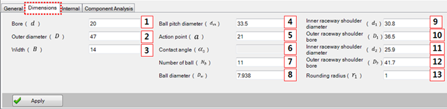
Figure 14.243: Parameters in the Angular contact ball bearing Dimensions tab
| Parameter | Description |
Dimension (Range) |
| 1. Bore | Use to set the bore. | Length(mm) |
| 2. Outer diameter | Use to set the outer diameter. | Length(mm) |
| 3. Width | Use to set the width. | Length(mm) |
| 4. Ball pitch diameter | Use to set the pitch diameter of the balls. | Length(mm) |
| 5. Action point | Use to set the action point. This value determines the contact angle. | Length(mm) |
| 6. Contact angle |
This value is calculated by the Action point. (Read only). | Angle(deg) |
| 7. Number of ball | Use to set the number of balls. | N/A |
| 8. Ball diameter | Use to set the diameter of balls. | Length(mm) |
| 9. Inner raceway shoulder diameter (L) | Use to set the shoulder lager diameter of the inner raceway. | Length(mm) |
| 10. Outer raceway shoulder bore (L) | Use to set the shoulder lager diameter of the outer raceway. | Length(mm) |
| 11. Inner raceway shoulder diameter (S) | Use to set the shoulder small diameter of the inner raceway. | Length(mm) |
| 12. Outer raceway shoulder bore (S) | Use to set the shoulder small diameter of the outer raceway. | Length(mm) |
| 13. Rounding radius | Use to set the rounding radius. | Length(mm) |
Refer to Figure 14.237: Component Analysis tab - Deep groove ball bearing designer (Stiffness).
Refer to Figure 14.237: Component Analysis tab - Deep groove ball bearing designer (Stiffness).
Figure 14.244: Reference data for Life factor
|
Contact angle | | e | | | ||
| X | Y | X | Y | |||
| 5 | 0.172 | 0.19 | 1 | 0 | 0.56 | 2.30 |
| 0.345 | 0.22 | 1 | 0 | 0.56 | 1.99 | |
| 0.689 | 0.26 | 1 | 0 | 0.56 | 1.71 | |
| 1.03 | 0.28 | 1 | 0 | 0.56 | 1.55 | |
| 1.38 | 0.30 | 1 | 0 | 0.56 | 1.45 | |
| 2.07 | 0.34 | 1 | 0 | 0.56 | 1.31 | |
| 3.45 | 0.38 | 1 | 0 | 0.56 | 1.15 | |
| 5.17 | 0.42 | 1 | 0 | 0.56 | 1.04 | |
| 6.89 | 0.44 | 1 | 0 | 0.56 | 1.00 | |
| 10 | 0.175 | 0.29 | 1 | 0 | 0.46 | 1.88 |
| 0.35 | 0.32 | 1 | 0 | 0.46 | 1.71 | |
| 0.7 | 0.36 | 1 | 0 | 0.46 | 1.52 | |
| 1.05 | 0.38 | 1 | 0 | 0.46 | 1.41 | |
| 1.4 | 0.4 | 1 | 0 | 0.46 | 1.34 | |
| 2.1 | 0.44 | 1 | 0 | 0.46 | 1.23 | |
| 3.5 | 0.49 | 1 | 0 | 0.46 | 1.1 | |
| 5.25 | 0.54 | 1 | 0 | 0.46 | 1.01 | |
| 7 | 0.54 | 1 | 0 | 0.46 | 1 | |
| 15 | 0.178 | 0.38 | 1 | 0 | 0.44 | 1.47 |
| 0.357 | 0.4 | 1 | 0 | 0.44 | 1.4 | |
| 0.714 | 0.43 | 1 | 0 | 0.44 | 1.3 | |
| 1.07 | 0.46 | 1 | 0 | 0.44 | 1.23 | |
| 1.43 | 0.47 | 1 | 0 | 0.44 | 1.19 | |
| 2.14 | 0.5 | 1 | 0 | 0.44 | 1.12 | |
| 3.57 | 0.55 | 1 | 0 | 0.44 | 1.02 | |
| 5.35 | 0.56 | 1 | 0 | 0.44 | 1 | |
| 7.14 | 0.56 | 1 | 0 | 0.44 | 1 | |
| 20 | - | 0.57 | 1 | 0 | 0.43 | 1 |
| 25 | - | 0.68 | 1 | 0 | 0.41 | 0.87 |
| 30 | - | 0.8 | 1 | 0 | 0.39 | 0.76 |
| 35 | - | 0.95 | 1 | 0 | 0.37 | 0.66 |
| 40 | - | 1.14 | 1 | 0 | 0.35 | 0.57 |
| 45 | - | 1.34 | 1 | 0 | 0.33 | 0.5 |
Refer to General.
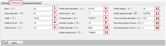
Figure 14.246: Parameters in Dimensions tab of Tapered Roller Bearing
| Parameter | Description |
Dimension (Range) |
| 1. Bore | Use to set the bore. | Length(mm) |
| 2. Outer diameter | Use to set the outer diameter. | Length(mm) |
| 3. Width | Use to set the width. | Length(mm) |
| 4. Width of Cone | Use to set the width of the cone. | Length(mm) |
| 5. Width of Cup | Use to set the width of the cup. | Length(mm) |
| 6. Roller pitch diameter | Use to set the pitch diameter of the roller. | Length(mm) |
| 7. Action point | Use to set the action point. This value determines the contact angle. | Length(mm) |
| 8. Contact angle |
This value is calculated by the Action point. (Read only) | Angle(deg) |
| 9. Number of roller | Use to set the number of rollers. | Length(mm) |
| 10. Roller diameter | Use to set the diameter of the rollers. | Length(mm) |
| 11. Roller center point | Use to set the roller center point. | Length(mm) |
| 12. Roller length | Use to set the roller length. | Length(mm) |
| 13. Roller tapered angle | Use to set the tapered angle for the roller. | Length(mm) |
| 14. Cone shoulder diameter | Use to set the diameter of the cone shoulder. | Length(mm) |
| 15. Rounding radius of cone | Use to set the rounding radius of the cone. | Length(mm) |
| 16. Rounding radius of cup | Use to set the rounding radius of the cup. | Length(mm) |
Refer to Figure 14.237: Component Analysis tab - Deep groove ball bearing designer (Stiffness).
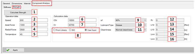
Figure 14.248: Parameters in Component Analysis - Strength tab for a Tapered roller bearing
| Parameter | Description |
Dimension (Range) |
| 1. Calculate Strength | Run the Motion Solver to calculate strength. | N/A |
| 2. Speed | Use to set the operating speed. | Rpm |
| 3. Axial Force | Use to set the operating axial force. | Force |
| 4. Radial Force | Use to set the operating radial force. | Force |
| 5. Temperature | Use to set the operating temperature. | ℃ |
| 6. C0r | Use to set the basic static radial load rating. | Force |
| 7. Cr | Use to set the basic dynamic radial load rating. | Force |
| 8. Basic load rating type | Use to select a basic load rating type of From Library, ISO or User Input. The From Library option allows you to reference stored libraries. Selecting this type will automatically change the basic load rating to the value contained in the bearing catalog. The ISO option makes and applies a calculation based on ISO. The User Input option references the user-input value. | N/A |
| 9. a1 | Use to select the reliability type. | % |
| 10. Lubricant Type | Use to select the lubrication type from , or . | N/A |
| 11. Cleanliness | Use to select the cleanliness type. | N/A |
| 12. Pr |
This value is calculated by input parameters. Pr : Dynamic equivalent radial load. | Force |
| 13. L10[Rev] | Basic rating life according to revolutions (ISO 281) | Rev |
| 14. L10[hr] | Basic rating life according to time (ISO 281) | Hr |
| 15. Lnm[Rev] | Modified rating life according to revolutions (ISO 281) | Rev |
| 16. Lnm[hr] | Modified rating life according to time (ISO 281) | Hr |
Rating lives are calculated using the equations below.
| (14–59) |
| (14–60) |
| (14–61) |
| (14–62) |
| (14–63) |


General
Refer to General.
Dimension
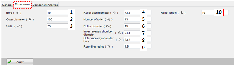
Figure 14.251: Parameters in the Cylindrical Roller Bearing Dimensions tab
| Parameter | Description |
Dimension (Range) |
| 1. Bore | Use to set the bore. | Length(mm) |
| 2. Outer diameter | Use to set the diameter of outer. | Length(mm) |
| 3. Width | Use to set the width. | Length(mm) |
| 4. Roller pitch diameter | Use to set the pitch diameter of roller. | Length(mm) |
| 5. Number of roller | Use to set the number of roller. | N/A |
| 6. Roller diameter | Use to set the diameter of roller | Length(mm) |
| 7. Inner raceway shoulder diameter (L) | Use to set the shoulder lager diameter of inner raceway. | Length(mm) |
| 8. Outer raceway shoulder bore (L) | Use to set the shoulder lager diameter of outer raceway. | Length(mm) |
| 9. Rounding radius | Use to set the rounding radius | Length(mm) |
| 10. Roller length | Use to set the roller length | Length(mm) |
Component Analysis
Stiffness
Refer to Figure 14.237: Component Analysis tab - Deep groove ball bearing designer (Stiffness).
Strength
Refer to Figure 14.237: Component Analysis tab - Deep groove ball bearing designer (Stiffness). Note that the equation is slightly different, when calculating Pr. Pr is defined by Fr.
