


From the Weld property dialog, parameters can be modified as shown in the figure and table below.
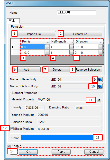
Figure 10.46: Description of parameters in the Weld property dialog
| Parameter | Symbol | Description | Dimension (Range) |
| 1. Import File | N/A | Use to import the text file for welding points. | N/A |
| 2. Export File | N/A | Use to export the defined welding points to the text file. | N/A |
| 3. Points | N/A | Use to set the welding points by Point Picker. |
Length (Real) |
| 4. Half-length | N/A | Use to set the half length for the weld. This determines the size of weld. See Weld Half-Length. |
Length (Real>0) |
| 5. Direction | N/A | Use to set the tangent direction by Direction Picker. The direction vector is used to determine the orientation of solid element. See Weld Tangent Direction. | N/A |
| 6. Add | N/A | Use to add a row of the point data. | N/A |
| 7. Delete | N/A | Use to delete a selected row of the point data. | N/A |
| 8. Reverse Selection | N/A | Use to reverse selecting state of the rows. | N/A |
| 9. Name of Base Body | N/A | Use to set the base nodal EasyFlex body by General Picker. | N/A |
| 10. name of Action Body | N/A | Use to set the action nodal EasyFlex body by General Picker. | N/A |
| 11. Material Property | N/A | Use to set the material property of the weld. | N/A |
| 12. Shear Modulus | N/A |
1. Check on to use the default value. 2. Check off to use a user defined value. | N/A |
| 13. Color | N/A | Use to set the color of weld. | N/A |
| 14. Control buttons | N/A | If all necessary parameters are set, the buttons are enabled. If you want to know the control buttons, refer to the Entity Properties Access and Modification. | N/A |