From the PTCV property dialog, the parameters of sliding motion, friction and connector can be modified as shown in the figures and table below. User subroutines are explained in Motion User Subroutine, where the constraint equation must be defined at the velocity level.
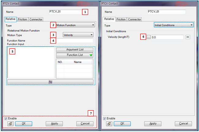
Figure 5.82: Description of Relative parameters in the PTCV property dialog
| Parameter | Symbol | Description | Dimension (Range) |
| 1. Name | N/A | Use to set the name of the PTCV. | N/A |
| 2. Type | N/A | Use to select a type for the sliding motion. When the type is , you can add the sliding motion to PTCV. When the type is , you can apply initial conditions to the PTCV. When the type is , you can add sliding motion at the velocity level using a user subroutine. | N/A |
| 3. Motion Type | N/A | Use to select the level of the constraint. When the type is , the sliding velocity between action marker and base curve is restricted to the specified function and initial displacement isn't required. When the type is , the sliding acceleration between action marker and base curve is restricted to the specified function and initial sliding velocity is required. | N/A |
| 4. Function Name | N/A | Use to set the name of the function expression. |
N/A (Character) |
| 5. Function Input |

| Use to set the function for the sliding motion. It is possible to select one of the pre-defined function expressions. For more information, refer to Function Expression. |
Length (Real) |
| 6. Velocity (length/T) |

| Use to set the initial sliding velocity between action marker and base curve. |
Length/Time (Real) |
| 7. Control buttons | N/A | If all necessary parameters are set, these buttons are enabled. For more information about the control buttons, refer to Entity Properties Access and Modification. | N/A |
Parameters for friction are as shown in the figure and table below. For more information on their usage, refer to Friction in PTCV in the Motion Theory Reference.
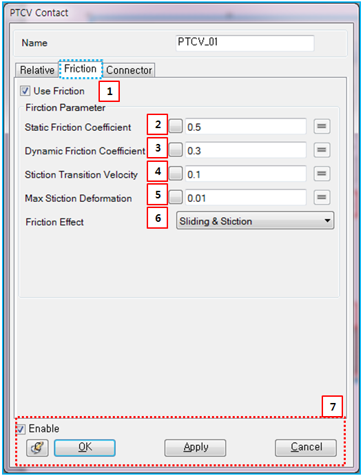
Figure 5.84: Description of Friction parameters in the PTCV property dialog
| Parameter | Symbol | Description | Dimension (Range) |
| 1. Use Friction | N/A | If this option is selected, the friction force will be applied at the contact point. | N/A |
| 2. Static Friction Coefficient |

| Use to set the static friction coefficient. |
N/A (Real>=0) |
| 3. Dynamic Friction Coefficient |

| Use to set the dynamic friction coefficient. |
N/A (Real>=0) |
| 4. Stiction Transient Velocity |

| Use to set the stiction transient velocity. |
Length/Time (Real>=0) |
| 5. Max Stiction Deformation |

| Use to set the maximum deformation under stiction. |
Length (Real>=0) |
| 6. Friction Effect | N/A | Use to select one of the friction effects. When is selected, the friction coefficient is calculated from Equation 5–4 ~ Equation 5–6. When is selected, the friction coefficient is calculated from Equation 5–6. When is selected, the friction coefficient is calculated from Equation 5–4. | N/A |
| 7. Control buttons | N/A | If all necessary parameters are set, these buttons are enabled. For more information about the control buttons, refer to Entity Properties Access and Modification. | N/A |
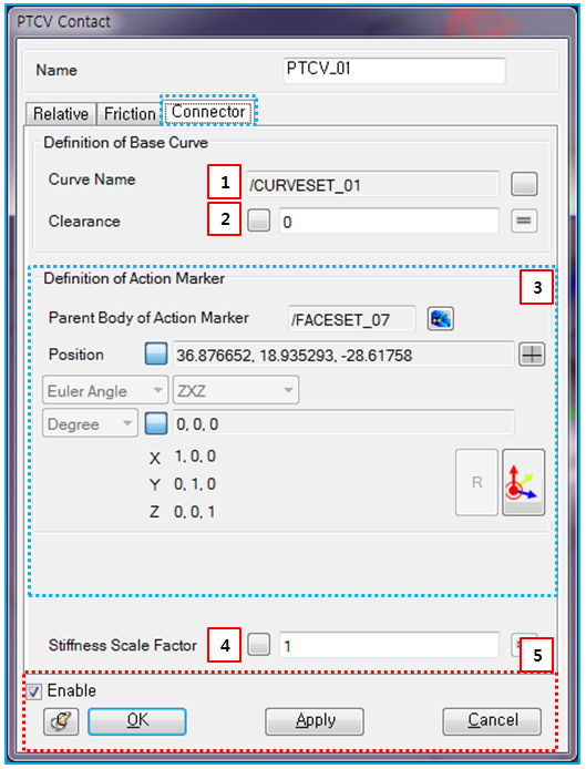
Connector parameters can be defined as shown in the table and figure below.
Figure 5.85: Description of Connector parameters in the PTCV property dialog
| Parameter | Symbol | Description | Dimension (Range) |
| 1. Curve Name | N/A | Use to set the curveset for the base curve. | N/A |
| 2. Clearance | N/A | Use to set the clearance. The action point is allowed to move within this clearance. This option is useful when considering the design or manufacturing tolerance. |
Length (Real>=0) |
| 3. Define Action Marker | N/A | Use to set the parent body, position, and orientation of the action marker. refer to Constraint Entity Connectors. | N/A |
| 4. Stiffness Scale Factor |

| Use to set the scale factor for the constrained force in Equation 5–98 in the Motion Theory Reference. |
N/A (Real>=0) |
| 5. Control buttons | N/A | If all necessary parameters are set, these buttons are enabled. For more information about the control buttons, refer to Entity Properties Access and Modification. | N/A |