


From the Curveset properties dialog, the parameters for generating the passing points on the Curveset can be modified as shown in the figure and table below.
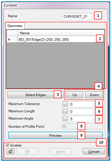
Figure 3.71: Parameters in the Curveset properties dialog
| Parameter | Symbol | Description | Dimension (Range) |
| 1. Name | N/A | Use to set the name of the Curveset. | N/A |
| 2. List of Edges | N/A | Use to display the names or colors of selected edges. The names of the edges are not editable. | N/A |
| 3. Select Edges | N/A | Use to add or remove the edges for the Curveset by using the MultiEdge Picker (Rigid Body) or Color Edge Picker. | N/A |
| 4. Up & Down | N/A | Use to move the location of the selected edge up and down the list. The sequence of edges is very important for representing the curve geometry. If the edges are not in the correct order, the generated curve from the Curveset will be discontinuous. | N/A |
| 5. Maximum Tolerance |

| Use to set the maximum error. For more information, see Passing Points Control in the Motion Theory Reference. |
Length (Real>0) |
| 6. Maximum Length |

| Use to set the maximum length. For more information, see Passing Points Control. |
Length (Real>0) |
| 7. Maximum Angle |

| Use to set the maximum relative angle. For more information, see Passing Points Control. |
Angle (Degree>0) |
| 8. Number of Profile Point | N/A | Use to show the number of passing points on the Curveset. |
N/A (Integer>0) |
| 9. Preview | N/A | Use to display the Curveset passing points on the screen. If you close the dialog, the preview will be hidden. | N/A |
| 10. Control buttons | N/A | If all necessary parameters are set, these buttons are enabled. For more information about the control buttons, refer to Entity Properties Access and Modification. | N/A |