


Force parameters are defined in the Concentrated Load property dialog as shown in the figure and table below.
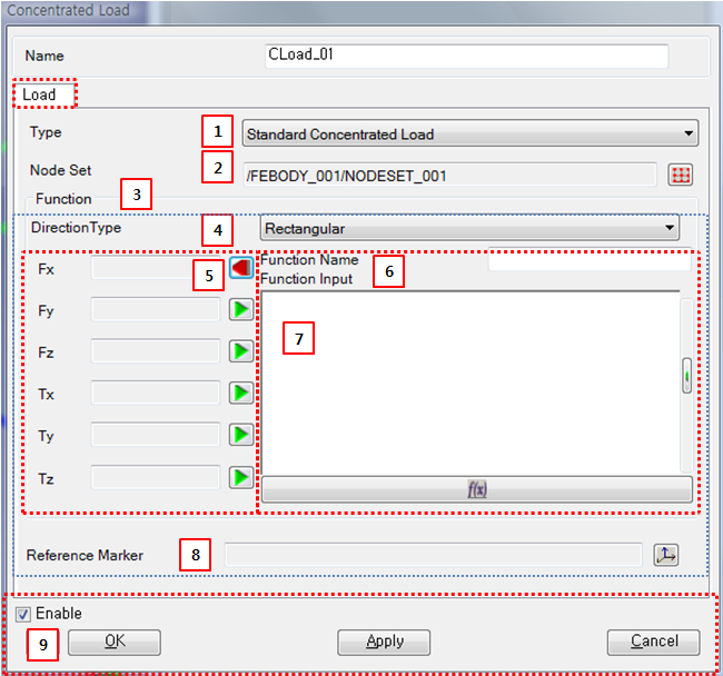
Figure 6.42: Description of parameters in the Concentrated Load property dialog
| Parameter | Symbol | Description | Dimension (Range) |
| 1. Type | N/A | Use to set the force and torque type. When is selected, the force and torque are defined by a Function Expression. When is selected, the force and torque are defined by a specified User Subroutine. For more information, refer to Concentrated Load User Subroutine | N/A |
| 2. Nodeset | N/A | Use to select a Nodeset using the General Picker. | N/A |
| 3. Function |  , , | Use to set six functions to define force and torque. If the function is not defined, the corresponding force or torque will be zero. | Force, Force*Length |
| 4. Direction Type | N/A | Use to set the direction type to either or . This determines the directions of the specified force and torque. For more information, refer to Concentrated Load. | N/A |
| 5. Function Manager | N/A | Open or close Function Expression. When the
 button is
clicked, Function Manager is opened. When
the button is
clicked, Function Manager is opened. When
the  button
is clicked, Function Manager is
closed. button
is clicked, Function Manager is
closed. | N/A |
| 6. Function Name | N/A | Use to set the name of the Function Expression. For more information on usage, refer to Function Expression Operation. | N/A |
| 7. Function Input | N/A | Use to input a Function Expression. For more information on usage, refer to Function Expression Operation. | N/A |
| 8. Reference Marker | N/A | Use to select a reference marker. The directions of force and torque are determined in the specified reference marker. If the reference marker is not defined, the inertia reference frame is used as the reference marker. | N/A |
| 9. Control buttons | N/A | If all necessary parameters are set, these buttons are enabled. For more information about the control buttons, refer to Entity Properties Access and Modification. | N/A |