


With the two points option, the welding points on two bodies and parameters can be defined as shown in the figure below and table.
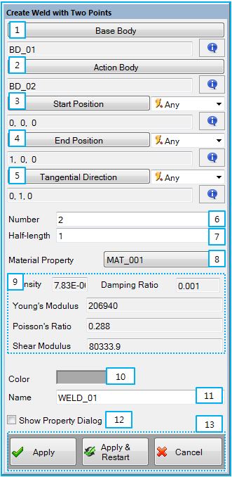
Figure 10.40: Description of parameters in the Weld with Two Points creation dialog
| Parameter | Description |
| 1. Base Body | Use to set the base nodal EasyFlex body by General Picker. |
| 2. Action Body | Use to set the action nodal EasyFlex body by General Picker. |
| 3. Start Position | Use to set the starting weld point by Point Picker. The first spot weld is located at this point. |
| 4. End Point | Use to set the end weld point by Point Picker. The last spot weld is located at this point. |
| 5. Tangential Direction | Use to set the tangent direction by Direction Picker. The direction vector is used to determine the orientation of solid element. See Weld Tangent Direction. |
| 6. Number | Use to set the number of spot weld. The weld points is defined as the number with equal space between the start point and the end point. |
| 7. Half-Length | Use to set the half length for the weld. This determines the size of weld. See Weld Half-Length. |
| 8. Material Property | Use to set the material property of the weld. |
| 9. Density… | Show the properties of defined material property. |
| 10. Color | Use to set the color of weld. |
| 11. Name | Use to set the name of weld. |
| 12. Show Property Dialog | Use to open the property dialog after finishing the creation operation. |
| 13. Control buttons | If all necessary parameters are set, the buttons are enabled. If you want to know the control buttons, refer to the Entity Creation. |