


Connecting properties such as action marker, base marker, reference marker, and parameters for the output channel are defined in the Output Channel creation dialog. Parameters in the dialog are defined as follows Figure 14.18: Rule to define the name of 3D CAD to be defined with a Bearing.
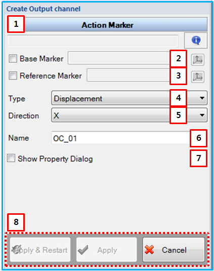
Figure 13.23: Description of parameters in the Output Channel creation dialog
| Parameter | Description |
| 1. Action Marker | Use to set a action marker by the general picker. This becomes an action marker of the input channel. |
| 2. Base Marker | Use to set a base marker by general picker. This becomes a base marker of output channel. If the base marker is not defined, the inertia reference frame is used as the base marker. |
| 3. Reference Marker | Use to set a reference marker by general picker. This becomes a reference marker. If the reference marker is not defined, the inertia reference frame is used as the reference marker. |
| 4. Type | Use to select type. You can select "Force", "Displacement", "Velocity", "Acceleration", "Angular Displacement", "Angular Velocity", "Angular Acceleration". |
| 5. Direction | Use to select direction. You can select "X", "Y", "Z", "Mag.". |
| 6. Name | Use to set a name of General contact. |
| 7. Show Property Dialog | Use to open the property dialog after finishing the creation operation. |
| 8. Control buttons | If all necessary parameters are set, the buttons are enabled. If you want to know the control buttons, refer the Entity Creation. |