


From the Output Channel property dialog, markers and parameters for the output channel can be modified as shown in the figure and table below.
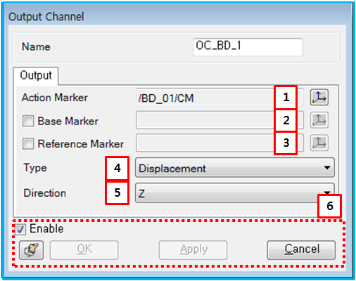
Figure 13.25: Description of parameters in the Output Channel property dialog
| Parameter | Symbol | Description | Dimension (Range) |
| 1. Action Marker | N/A | Use to set an action marker by the general picker. This becomes an action marker of the input channel. | N/A |
| 2. Base Marker | N/A | Use to set a base marker by general picker. This becomes a base marker of output channel. If the base marker is not defined, the inertia reference frame is used as the base marker. | N/A |
| 3. Reference Marker | N/A | Use to set a reference marker by general picker. This becomes a reference marker. If the reference marker is not defined, the inertia reference frame is used as the reference marker. | N/A |
| 4. Type | N/A | Use to select type. You can select "Displacement", "Velocity", "Acceleration", "Angular Displacement", "Angular Velocity", "Angular Acceleration". When the type is "Displacement" or "Angular Displacement", output is calculated in the same way as displacement functions of function expression. When the type is "Velocity" or "Angular Velocity", output is calculated in the same way as velocity functions of function expression. When the type is "Acceleration" or "Angular Acceleration", output is calculated in the same way as acceleration functions of function express. You want to know more information, refer the Function Expression. | N/A |
| 5. Direction | N/A | Use to select direction. You can select "X", "Y", "Z", "Mag.". Use to calculate output about direction between markers. If you select "Displacement" by type and "X" by direction, the output is calculated in the same way as "DX" of function express. You want to know more information, refer the Function Expression. | N/A |