


Connecting properties such as the acting and reacting bodies, the location on the bodies and the rotational direction are defined in the General Bearing creation dialog, as shown in the figure below. When creating the force, two markers are created simultaneously to represent this. The z-axes of the markers are same as the specified shaft direction. The base body must be the outer race or housing of the bearing system and the action body must be the inner race or shaft. Parameters in the dialog are defined in the table below.
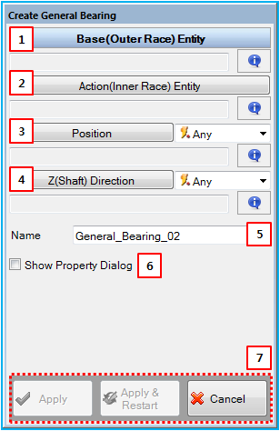
Figure 6.118: Description of parameters in the General Bearing creation dialog
| Parameter | Description |
| 1. Base (Outer Race) Entity | Use to select a reacting body using the General Picker. This defines the parent body of the base marker. |
| 2. Action (Inner Race) Entity | Use to select an acting body using the General Picker. This defines the parent body of the action marker. |
| 3. Position | Use to set the location on the base and action bodies using the Point Picker. This defines positions of the base and action markers. |
| 4. Z(Shaft) Direction | Use to set the direction on the base and action bodies using the Direction Picker. This defines z-axes of the base and action markers. |
| 5. Name | Use to set the name of the General Bearing object. |
| 6. Show Property Dialog | Use to open the property dialog after finishing the creation operation. |
| 7. Control buttons | If all necessary parameters are set, these buttons are enabled. For more information about the control buttons, refer to Entity Creation. |