


Surface is a type of geometry that can be used to create solid features. Surface tools are available on the Surface toolbar. You can create surfaces by these methods:
- Plane
From a coordinate system and define the length and width, or create by 3 points.
- Cylinder
From a coordinate system and define the radius, start and end angle, bottom and top height, or create by specifying bottom, top center.
- Cone
From a coordinate system, and define the semi-spine angle, bottom radius, start and end angle, bottom and top height, or create by specifying bottom, top center and radius.
- Sphere
From a coordinate system, and define the radius and three angles parameters, or create by select center point and another point on sphere or define the radius.
- Torus
From a coordinate system and define the path and profile radius, and other three angles parameters.
- Ellipsoid
From a coordinate system and define the A, B, C radius, and other U, V angles.
- Fill Plane
Insert a planar surface from a sketch or from a set of closed edges that lie on a plane, or a group of points
- Extrude
Given an edge or wire as profile, an axis as direction, it linearly extrudes a surface or shell.
- Revolve
Given an edge or wire as profile, an axis as rotational direction, it rotates a surface or shell.
- Sweep
Given an edge or wire as profile curve, another edge or wire as path curve, it sweeps a surface or shell
- Loft
Give a set of edge or wire, it loft a surface or shell. The two ends of the curves group can be replace by point. Such as you can create a cone surface by loft a circle and a point.
- N-Side Surface
Give a set of connected edges or wires, to fill a surface. You can add boundary constraint such as C1, C2.
- Patch Surface
Give 3, 4 or 5 edges, create a flat, middle, round surface.
- Bridge
Select edges from one face and select another edges from another face, and create a bridge surface to make two faces connected together.
- Combine
Select neighbour faces or shell, fit a surface which combine them together.
- Fit Surface
Fit a surface from point cloud or mesh.
- Middle Surface
Give a pair of surfaces or a solid shape, create middle surfaces.
- Surface Morph
Modify surface by control points, points on surface or profile curves.
- Fit Primary
Select nodes or elements, fit Plane, Cylinder, Cone, Sphere, Extrude Surface or Revolve Surface.
- Break Surface
Define U, V parameters or number of ISO split lines, break surface into pieces.
You can modify surfaces in the following ways:
You can use surfaces in the following ways:
Select surface edges and vertices to use as a sweep guide curve and path.
Create a solid or cut feature by thickening a surface.
Extrude a solid or cut feature with the end condition Up to Surface or Offset from Surface.
Create a solid feature by thickening surfaces that have been knit into a closed volume.
Replace a face with a surface
You can create a plane surface by parameters, 3 points or fit points. Click View, Geom Surface to toggle the display of individual surface.
To create a plane: Click Plane (Surface toolbar) or click Geometry, Surface, Plane.
In the dialog, select the type of you want to create the plane:
- Parameters
Create a plane by parameters. The parameters contain a local coordinate system, start and end X, Y coordinates on the local coordinate system. By default, the coordinate system is set as the standard global coordinate system. You can also sketch a rectangle plane onto any plane when "Sketch on Plane" is checked.
Create a plane using local coordinate system
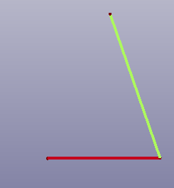
- 3 Points
Create a plane by passing through three points. You can also scale the plane by setting "Scale" parameter.
Create a plane using 3 points
- Fit Plane
Create a least square error plane by fitting three or more points. You can also scale the plane by setting "Scale" parameter. To sample all points from edge or face, check "Whole Edge/Face".
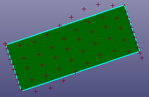
Fit a plane by points
- Point/Normal
Create a plane by an origin point and a normal vector.
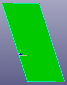
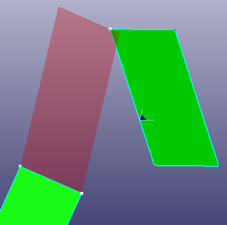
- Parallelogram
Create a parallelogram plane by two connected curves.

a. Two lines
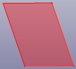
b. Parallelogram face
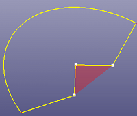
- IsoTrapezoid
Create isotrapezoid plane face by two connect curves.
a. Two lines
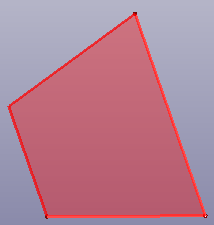
b. Trapezoid face
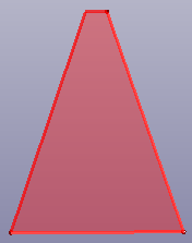
c. Trapezoid face with "Swap" option
- RegPolygon
Create a regular polygon's plane by side number and side length.
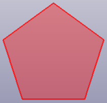
a. Pentagon
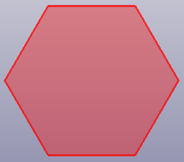
b. Hexagon
You can create a cylinder surface by parameters. Click View, Geom Surface to toggle the display of individual surface.
To create a cylinder: Click Cylinder(Surface toolbar) or click Geometry, Surface, Cylinder.
In the dialog, select the type of you want to create the cylinder:
- Parameters
Create a cylinder by parameters. The parameters contain a local coordinate system, start and end angle, bottom and top height on the local coordinate system. By default, the coordinate system is set as the standard global coordinate system.
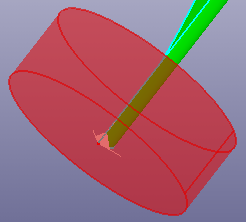
Create a half cylinder surface using a local coordinate system
- Bot/Top Pnt
Select two points as the bottom and top centers of the cylinder. And define the radius, start and end angle.
By bottom and top center
You can create a cone surface by parameters. Click View, Geom Surface to toggle the display of individual surface.
To create a cone: Click Cone(Surface toolbar) or click Geometry, Surface, Cone.
In the dialog, select the type of you want to create the cone:
- Parameters
Create a cone by parameters. The parameters contains:
A local coordinate system. By default, it is set as the global standard coordinate sytem.
Semi-angle of the apex. The apex of the cone is on the positive side of the "main Axis" of the coordinate system if the half-angle is positive, and on the negative side if the half-angle is negative.
Bottom radius.
Start and end angle.
Bottom and top height.
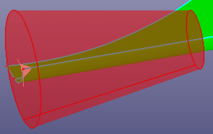
Create a cone surface using a local coordinate system
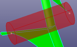
- Bot/Top Pnt
Select two points as the bottom and top centers of the cone. And define the bottom and top radius, start and end angle.
By bottom and top center
You can create a sphere surface by parameters. Click View, Geom Surface to toggle the display of individual surface.
To create a sphere: Click Sphere(Surface toolbar) or click Geometry, Surface, Sphere.
In the dialog, select the type to create the sphere:
- Parameters
Create a sphere by parameters. The parameters contains:
A local coordinate system. By default, it is set as the global standard coordinate system.
Radius.
U start/end angle. Input angle between [-90.0 ~ 90.0).
V start/end angle. Input angle between [-180.0 ~ 180.0).
Create an unclosed sphere surface using a local coordinate system
- Center Point
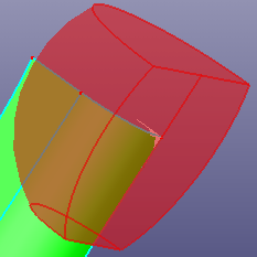
Select a point as the center of the sphere. Select another point as the point on the surface or define the radius directly.
By center and another point
- Tetrahedron
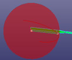
Select four points to create circumscribed or inscribed sphere.
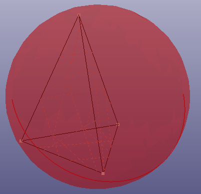
a. circumscribed sphere
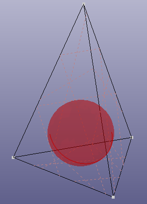
b. inscribed sphere
You can create a torus surface by parameters. Click View, Geom Surface to toggle the display of individual surface.
To create a torus: Click Torus(Surface toolbar) or click Geometry, Surface, Torus.
To create a torus, using following parameters:
A local coordinate system. By default, it is set as the global standard coordinate system.
Path radius.
Profile radius.
U start/end angle. Input angle between [-180.0 ~ 180.0).
V start/end angle. Input angle between [-180.0 ~ 180.0).
Create a unclosed torus surface using a local coordinate system
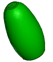
You can create an ellipsoid surface by parameters. Click View, Geom Surface to toggle the display of individual surface.
To create a ellipsoid: Click Ellipsoid(Surface toolbar) or click Geometry, Surface, Ellipsoid.
To create an ellipsoid, using following parameters:
A local coordinate system. By default, it is set as the global standard coordinate system.
A radius. Radius in X direction.
B radius. Radius in Y direction.
C radius. Radius in Z direction.
U start/end angle. Input angle between [0 ~ 360.0].
V start/end angle. Input angle between [-90.0 ~ 90.0].
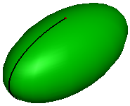
Create an ellipsoid surface using a local coordinate system
You can create a planar surface by a group of points or connected edges. Click View, Geom Surface to toggle the display of individual surface.
To fill a planar surface: Click Fill Plane (Surface toolbar) or click Geometry, Surface, Fill Plane .
To fill plan, using following two methods:
- By Edges
If there are lots of edges to be selected, you can click button "Search" to search neighbour edges with the selected edges in the list box. If all the selected edges are not strictly laid on the plane, you can check "Allow Projection" to project all selected edges to the a fit plane internally.
By edges
- By Points
If all the selected points are not strictly laid on the plane, you can check "Allow Projection" to project all selected points to the internally fit plane.
By points.
You can create a extrude surface by a profile curve and a direction. Click View, Geom Surface to toggle the display of individual surface.
To create a extrude surface: Click Extrude (Surface toolbar) or click Geometry, Surface, Extrude.
To extrude a surface, by following steps:
Profile Shape. Select edges or wires as the profile.
Extrude Direction. Select an axis or a line shape as the direction. If the profile curve is planar, the default direction is the normal of the plane which profile curve locates at.
Start and End Distance. Define the profile's start and end position. You can directly edit these two parameters by dragging the extrude bar (two red arrows).
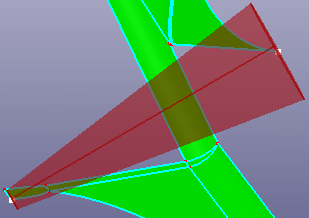
Extrude To. To end extruding surface at the specified position, select a point, curve or surface into "Extrude To" as termination condition. To extrude as a draft surface, check "Draft" and define the draft angle.
a. Extrude surface
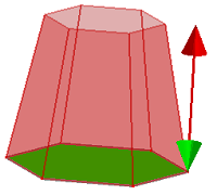
b. Draft surface with angle 10.0
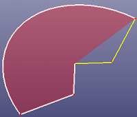
You can create a revolve surface by a profile curve and an axis. Click View, Geom Surface to toggle the display of individual surface.
To create a revolve surface: Click Revolve (Surface toolbar) or click Geometry, Surface, Revolve .
To create a revolve surface, by following steps:
Profile Shape. Select an edge or a wire as the profile curve.
Revolve Axis. Select a Ref-Axis or a line as the axis.
Start and End Angle. Define the profile's start and end position.
Revolve To. To stop revolving at specified position, select a point, curve or surface as destination.
Revolve surface
You can create a sweep surface by a profile curve and a path curve. Click View, Geom Surface to toggle the display of individual surface.
To open sweep surface: Click Sweep (Surface toolbar) or click Geometry, Surface, Sweep.
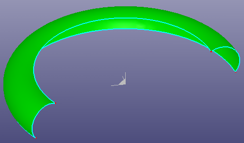
To create a sweep surface, select an edge or wire as profile curve, select an edge or wire as path curve. If you want to make a circle as profile, check "Circle as Profile". Select a FEM beam as path, check "Pick Beam as Path".
You can check "End Constraint" to make profile curve connected with path curve on one end. If the path curve is noisy, you can also check "Smooth Path" to make the path smooth. To set surface continuity, check "Set Continuity".
"Fix Coordinate System" and "Scale" are the options to control the shape during sweeping.
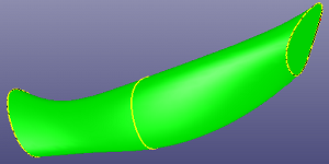
a. using a circle as profile, a helix curve as path curve, get a sweep surface
b. result by check "End Constraint"
a. The path curve (brown) is a C0 curve
b. Sweep surface setting continuity as C0
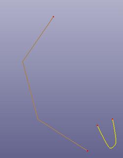
Loft is a face or shell passing through a set of sections in a given sequence. Usually sections are edges or wires, but the first and the last sections may be vertices (punctual sections). Click View, Geom Surface to toggle the display of individual surface.
To open loft surface: Click Loft (Surface toolbar) or click Geometry, Surface, Loft.
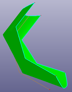
To create a loft surface, select a set of sections in a given sequence. Usually sections are edges or wires, but the first and the last sections may be vertices. To make the surface closed, check "Closed" to make the final section is the same with the first section. When selecting profile curves, there are a serial guided points to show, the guided points match two neighbour curves' end points' direction. You can check "Auto Align" to align profile curves automatically. To create ruled surface, check "Ruled" option.
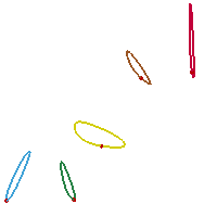
a. six profile curves
b. loft surface
c. loft surface by one vertex and two profile curves
d. loft surface after checking "Auto Align"
N-Side surface is to build a face from a set of edges defining the bounds of the face and some constraints the surface of the face has to satisfy.
Click View, Geom Surface to toggle the display of individual surface.
To open N-Side surface: Click N-Side Surface (Surface toolbar) or click Geometry, Surface, N-Side Surface.
To create a N-Side surface, select a set of edges or wires as the boundary of the face. You can select "Continuity 0", "Continuity 1" and "Uniform Fit" to set the constraint conditions.
Continuity 0: the surface will pass all the edges.
Continuity 1: the surface will pass all the edges and try to respect tangency with the first face of the edge.
Uniform Fit: the surface will pass all the edges. It will fit a base-surface firstly, and try to use all the selected edges to trim base-surface.
Simple Fit: Simple Fit uses different fitting algorithm compared to Uniform Fit.
You can check "Auto Close" to constraint the edges or wires connected with each other when "Continuity 0" or "Uniform Fit" is selected, and check "Smooth" option to smooth boundary curves.
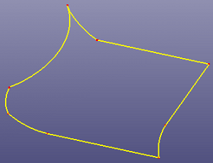
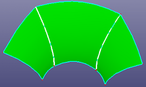
a. 8 boundary curves
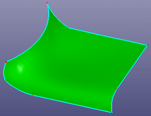
b. N-side surface
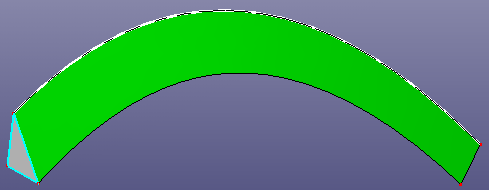
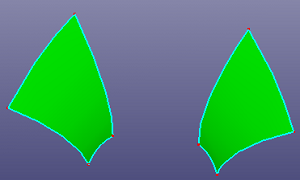
Patch surface is for constructing a B-Spline surface filled from contiguous B-Spline curves which form its boundaries. The algorithm accepts two, three or four B-Spline curves as the boundaries of the target surface. A range of filling styles - more or less rounded, more or less flat - is available. Click View, Geom Surface to toggle the display of individual surface.
To open patch surface: Click Patch Surface (Surface toolbar) or click Geometry, Surface, Patch Surface.
To create a patch surface,
Select patch type: Flat, Middle, Round and Constrained. "Flat" type has the flattest shape. "Middle" type is Coons surface which is a little rounded style of patch. "Round" type is of curved surface which is the most rounded surface. Constrained will use fit method to get a proper surface.
Select 2, 3 or 4 edges.
If the raw curves are noisy, check the "Smooth Curves" option.
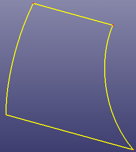
a. Four boundary curves
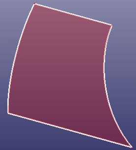
b. Patch surface using "Flat" option
To create a blend surface which connect two faces is named bridge surface. Click View, Geom Surface to toggle the display of individual surface.
To open bridge surface: Click Bridge two faces (Surface toolbar) or click Geometry, Surface, Bridge two faces .
To create a bridge surface,
Select edge(s) on one face. Select other edge(s) on another face.
Select the bridge surface constraint conditions: Continuity 0,1.
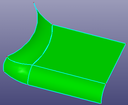
a. two faces
b. bridge surface by selecting two edges, continuity set as 1
Surface Combine is to combine selected neighbour faces or shell into a single surface. Click View, Geom Surface to toggle the display of individual surface.
To open combine surface: Click Combine (Surface toolbar) or click Geometry, Surface, Combine.
To make a combine surface,
Select faces or shell which should be grouped together.
Define number of U, V control points and degrees, max tolerance and smoothness.
Select result surface type: Natural Surface or Trimmed Face.
Check "Replace Raw Faces" to remove raw faces. If it's unchecked, it means adding result face only. Check "Preview" to preview result.
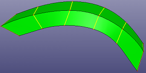
a. 4 faces
b. combine surface
Surface Fit is to approximating a surface by select a point cloud or a set of triangles/quads. Click View, Geom Surface to toggle the display of individual surface.
To open Fit from Pnts/Mesh surface: Click Fit from Pnts/Mesh (Surface toolbar) or click Geometry, Surface,Fit from Pnts/Mesh.
To fit surface from pnts/mesh,
Select source type: By Points or By Mesh.
Define number of U, V control points and degrees, maximum and average tolerance, smoothness.
If select "By Points", there provides a reference plane, it's normal is dx,dy and dz, you can modify this normal to refit the surface.
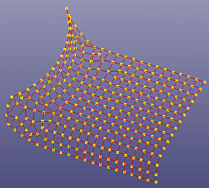
a. select nodes by part
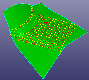
b. fit surface by points
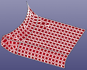
a. select elements by part
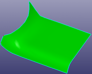
b. fit surface by mesh
Middle surface is a simplification representation of complex solid shapes. It's used most for model simplification.
To open Middle Surface: Click Middle Surface (Surface toolbar) or click Geometry, Surface, Middle Surface.
In the dialog, select the type of you want to create the middle surface:
- By Surfaces
Select two faces to create a middle surface between them. When "Multi Surfs" is checked, you can select multiple surfaces into each face group and create the middle surface between these two face groups.
a. middle surface between two faces
b. middle surface between two face groups
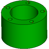
- By Solid
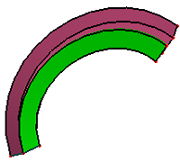
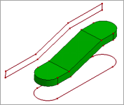
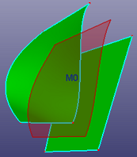
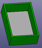
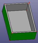
Select a shell or solid shape, and search mid-surfaces pairs and create multiple middle surfaces between each pair. When "Stitch Mid-Surfs" is checked, it will try to stitch each middle surfaces together. To make searching more strictly, check "Search Pairs Strictly".
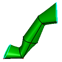
a. raw solid shape
b. middle surfaces of the raw solid shape, "Stitch Mid-Surfs" is checked.
- Top & Bottom
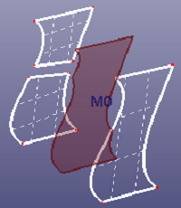
Select a face from shell or solid shape. It will search mid-surfaces pairs and find the same level surfaces from the face pairs with the seed face.
a. select a seed face
b. searched same level surfaces on the same solid
- Shell by Angle
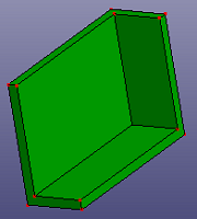
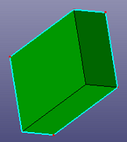
Select a face from shell or solid shape. It will search near faces which the angle difference is under given tolerance from the same shell or solid shape.
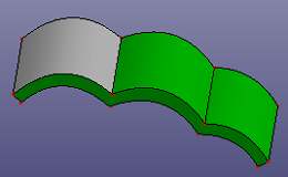
a. select a seed face
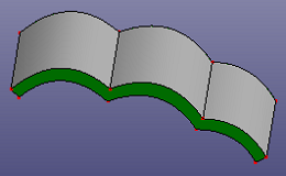
b. searched same level surfaces on the same solid, the angle tolerance is set as 70.0
Middle surface is a simplification representation of complex solid shapes. It's used most for model simplification.
To open Middle Surface: Click Middle Surface (Surface toolbar) or click Geometry, Surface, Middle Surface.
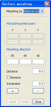
In the dialog, select the type of you want to morph surface:
Point on Surface
Select two faces to create a middle surface between them. When "Multi Surfs" is checked, you can select multiple surfaces into each face group and create the middle surface between these two face groups.
- Picked/morphed point
Use General Selection Interface to pick a point on a surface, the surface will be selected, (x, y, z) coordinate of the picked/morphed point will be displayed.
- Morphing direction
surface point is morphed by this direction (dx, dy, dz).
- Distance
surface point morphing distance.
- Reverse
When this check box is checked, the surface point will be morphed by opposite direction.
- Increment
surface morphing distance applied when you click button '+' or "-".
- +
surface is morphed by the distance of increment value.
- -
surface is morphed by the distance of increment value in reversed morphing direction.
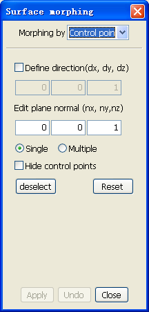
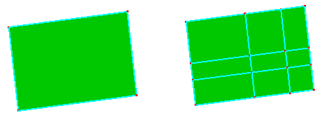
Control Point
Surface Fit Primary is a tool to approximate plane, cylinder, cone, sphere, extrude or revolve surface by point cloud or elements. Click View, Geom Surface to toggle the display of individual surface.
To open Fit Primary: Click Fit Primary (Surface toolbar) or click Geometry, Surface,Fit Primary.
To fit primary surface from pnts/mesh,
Select By Point or By Element. Extrude or Revolve fitting are only available under By Element is checked.
Select surface type: Plane, Cylinder, Cone, Sphere, Extrude or Revolve.
You can break surface into pieces by defining U, V parameters or defining number of ISO split lines. Click View, Geom Surface to toggle the display of individual surface.
To break a surface: Click Break(Surface toolbar) or click Geometry, Surface, Break.
In the dialog, select the type of you want to break by:
- Split
Select a surface and define the U, V parameters to split it. When "N-Segments" is checked, use number of ISO split segments to break surface. To create only ISO curves, check "Only ISO Curves". To create only parameter points, check "Only Sample Pnts".
Break surface using Split
- UV Bound
To only extract part of surface, use UV Bound.