


You can create several types of curves by using these methods:
- Points
From parameter, sketch or generated by projecting point to curve or surface
- Line
From two points parameters, sketch, two selected points, or generated by one point and one direction
- Circle
From parameters, sketch, from a point, an axis and specified radius, from coordinate and radius, or generated by 3 points.
- Circular Arc
From parameters, sketch, from a point, an axis, specified radius,start and end angle, from coordinate, radius, start and end angles, or generated by 3 points.
- Ellipse
From parameters, sketch, from a point, an axis, specified major and minor radius, or from coordinate, major and minor radius.
- Elliptical Arc
From parameters, sketch, from a point, an axis, specified major, minor radius,start and end angle, from coordinate, major and minor radius, start and end angles
- BSpline Curve
Interpolate points to construct planar or spacial B-spline curve or by interpolation points on surface to construct curve on surface.
- Helix
By specifying a circular sketch, number of revolutions, and height
- Composite Curve
From a combination of connected curves or boundaries of shell
- Break Curve
Break curve into several sub curves using angle or specified points
- Merge Curve
Merger neighbour curves into one single b-spline curve.
- Bridge Curve
Make a new curve which bridge two neighbour curves naturally
- Smooth Curve
Make noisy curve into a smooth curve
- Middle Curve
Generate middle curve or point from two selected curves or points
- Morph Curve
Morph curve by segment, control points or points on curve
- Fillet Curve
Create fillet curve between two neighbour curves
- Sketch
Using sketch method to create or modify line, arc or b-spline curve onto a sketch plane.
- Convert
Convert curve to/from XYZ, IGES, STEP, DXF, VDA files. Convert curve to/from keyword.
- Parabola
From parameters, from a point, an axis, or from coordinate, focal.
- Hyperbola
From parameters, or from coordinate, major and minor radius.
- Function
Create piecewise curve by parameter definition, such as polynomial curve.
- Polygon
Create regular polygon by side number and side length or center length.
- Fit
Fit points to point, line, circle, ellipse, parabola, hyperbola and B-Spline curve.
You can then use the curves to create surface or solid model features. For example, you can use a curve as the profile or path curve for a sweep feature, as the trim tool for trimming the surface feature, as a parting line for a draft feature, and so on.
You can turn the display of curves on or off. To toggle the display of curves, Click View, Geom Curves.
To hide or show individual curves: Right-click the curve in the graphics area or in the Feature Tree, select Hide or Show. Or you can go to Geometry Tools->Management, select the curve ID, then click "(un)Blank". You can also finish it on Component And Sel. Part Dialog.
You can create points to use as construction objects. Click View, Points to toggle the display of individual points/vertices.
To create a point, Click Point(Curve toolbar) or click Geometry->Curve->Point.
In the dialog, select the type of you want to create the point:
- Parameters
Create a point by parameter. You can also select a local coordinate system (LCS). You can also sketch points directly onto any plane by checking Sketch on Plane.
- Project to Cur
Create points by projecting the selected point onto the selected curve.
- Project to Surf
Create points by projecting the selected point onto the selected surface.
- Edit Curve End
Edit curve's end by selecting vertex and freely dragging. The curve must be from independent edge or edge from independent wire.
- Edit Ctrl-Pnt
Edit b-spline curve or b-spline surface by modify their control points. You can modify the curve or surface by dragging, adding or removing control points.
- Batch Input
Batch creating points by inputting a serial of coordinates. It will automatically analysis the input text. Such as pasting "(23, 12.1, 1.0e-3) [123.00 3 8" into the text control, and click Apply. It will generate two points (23, 12.1, 0.001) and (123, 3, 8).
- Tangent on Curve
Search to find points in the curve that have the same tangent vector as the direction of the selected line.
You can create line by several construction types. Click View, Geom Curve to toggle the display of individual curve.
To create a point: Click Line(Curve toolbar) or click Geometry, Curve, Line.
In the dialog, select the type of you want to create the line:
- Parameters
Create a line by two points' parameters. You can also sketch lines onto any plane when "Sketch" is checked.
- Point/Point
Create a line or multiple connected lines by select points in order. If more than two points selected, you can check "Closed" to make the loop close. If lots of unsort points are area selected into the list box, you can check "Sort Points" and it will automatically sort points according distance gap.
- Point/Axis.
Create a line by a point and a direction, the distance define the length of the line segment. If the distance is negative, the line direction will be reversed. "Project" option will project the selected points to the selected edge/direction vector, and the results are line segments.
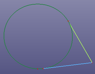
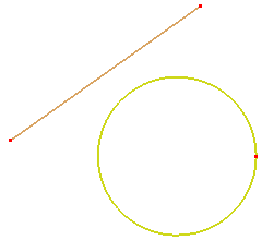
- Point/Circle
Create two lines which pass the point and tangent with the circle. The selected point must locate at the plane of the circle.
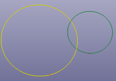
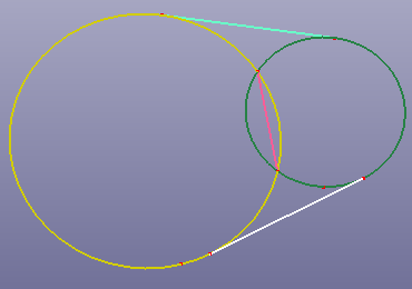
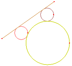
- Circle/Circle
Create lines which tangent with two circles. If two circles intersect with each other, it will also create the intersecting line. The selected two circles must locate at the same plane. 'Centers Line' will make a line segment between two centers of circles.
- Middle Line
Create lines which pass the intersection of two selected lines and have the same angle with two selected lines. 'Middle Curve Line' will make a line between centers of two virtual boundaries.
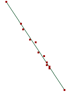
- Fit Line
Fit a line segment by the selected points using least square fitting method (LSQ). 'Scale' will scale the fit line to proper length. 'Whole Edge' will dense more points in the selected curve to fit.
- Extend Line
Extend a line segment by distance, ratio or destination objects.
You can create circle by several construction types. Click View, Geom Curve to toggle the display of individual curve.
To create a circle: Click Circle (Curve toolbar) or click Geometry, Curve, Circle.
In the dialog, select the type of you want to create the circle:
- Parameters
Create a circle by center, normal and radius parameters. You can also sketch circles onto any plane when "Sketch on Plane" is checked. "Radius" button is an option to change its value to "Radius", "Circumference" or "Area".
- Point/Axis
Create a circle by select a center point, an axis and define the radius. You can select any curve(non-linear curve), and the selected point will be projected to the edge and the axis will be the tangent vector of the projection position on the curve. You can also check the "Rotate" option, and the selected point will rotate with the axis. "Radius" button is an option to change its value to "Radius", "Circumference" or "Area".
Select a vertex and an edge. The vertex is one end of the edge. The circle's center will locate at the vertex and the normal of the circle's plane is the tangent of the vertex on the edge
Select a vertex and an edge. The vertex is not on the edge. The circle's center will locate at the vertex and the normal of the circle's plane is the tangent of the vertex projected on the edge
- Coordinate System
Create a circle by selecting a coordinate system, and define the radius. "Radius" button is an option to change its value to "Radius", "Circumference" or "Area".
- 3 Points
Create a circle by selecting 3 points. When "Inscribed Circle" is checked, it will create an inscribed circle. "Center/Start/End" will make a circle by different meaning. Suppose the three points are P1, P2 and P3. P1 will be the center of the circle, and P2 will locate at the bound of the circle. That means the radius will be |P2-P1|. P3 will be used to calculate the axis vector of the circle. The axis vector is (P2-P1)*(P3-P1).
- Tan Line/Circle
Create circles which are tangent with the selected line and another circle, it also need to define the radius. "Radius" button is an option to change its value to "Radius", "Circumference" or "Area".
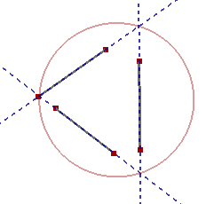
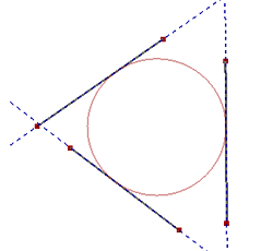
- 3 Lines
Create circumscribed or inscribed circles by three lines.
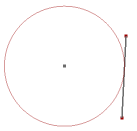
- Center/Tangent
Select a point and a line. The point will be the center of the circle, and the circle will be tangent with the selected line.
You can create circular arc by several construction types. Click View, Geom Curve to toggle the display of individual curve.
To create a circular arc: Click Circular Arc (Curve toolbar) or click Geometry, Curve, Circular Arc.
In the dialog, select the type of you want to create the circular arc:
- Parameters
Create a circular arc by center, normal, radius, start and end angle. You can also sketch circular arcs when "Sketch on Plane" is checked.
- Point/Axis
Create a circular arc by select a center point, an axis and define the radius, start and end angle. "Rotate" option will make the selected point rotate with the axis.
- Coordinate System
Create a circular arc by selecting a coordinate system, and define the radius, start and end angle.
- 3 Points
Create a circular arc by 3 points. "Center/Start/End" will make a circle by different meaning. Suppose the three points are P1, P2 and P3. P1 will be the center of the circle, and P2 will locate at one end of the circular arc. That means the radius will be |P2-P1|. P3 will be used to calculate the axis vector and the end point of the circular arc. The axis vector is (P2-P1)*(P3-P1).
- Tangent Two Lines
Create a circular arc which is tangent with two selected lines and the radius is given firstly. If two lines are parallel with each other, the radius of the tangent circular arc will be calculated automatically. "Ref Position" will make the circular arc pass through the selected point.
- Two Pnts/One Line
Create a circular arc which tangent with the selected line and pass two selected points.
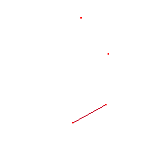
a. Select one line and two points
b. Create tangent arc
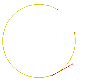
- Two Pnts/Radius
Create circular arcs passing two selected points and using defined radius. The circular arcs will located at a default plane calculated by two points.
a. Select two points
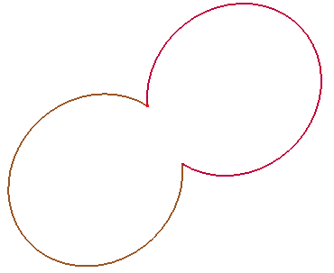
b. Create circular arcs using radius 1.0
You can create ellipse by several construction types. Click View, Geom Curve to toggle the display of individual curve.
To create an ellipse: Click Ellipse (Curve toolbar) or click Geometry, Curve, Ellipse.
In the dialog, select the type of you want to create the ellipse:
- Parameters
Create an ellipse by center, normal, major and minor radius. You can also sketch ellipse when "Sketch on Plane" is checked.
- Point/Axis
Create an ellipse by select a center point, an axis and define the major and minor radius.
- Coordinate System
Create an ellipse by select a coordinate system, and define the major and minor radius.
You can create elliptical arc by several construction types. Click View, Geom Curve to toggle the display of individual curve.
To create an elliptical arc: Click Elliptical Arc (Curve toolbar) or click Geometry, Curve, Elliptical Arc.
In the dialog, select the type of you want to create the elliptical arc:
- Parameters
Create an elliptical arc by center, normal, major, minor radius, start and end angle parameters. You can also sketch elliptical arcs when "Sketch on Plane" is checked.
- Point/Axis
Create an elliptical arc by select a center point, an axis and define the major and minor radius, start and end angle.
- Coordinate System
Create an elliptical arc by select a coordinate system, and define the major and minor radius, start and end angle.
You can create B-spline curve by several construction types. Click View, Geom Curve to toggle the display of individual curve.
To create a B-spline curve: Click B-Spline Curve (Curve toolbar) or click Geometry, Curve, B-Spline Curve .
In the B-Spline Curve dialog, define two types b-spline curves: Piecewise and Natural. Piecewise b-spline curve is a polygon chained by points, so it's C0 continuity. Natural b-spline curve looks more smooth than Piecewise curve, its degree is usually set as 3.
In the dialog, select the type of you want to create the B-spline curve:
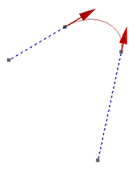
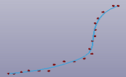
- Interpolate Pnts
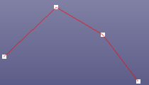
Create a B-spline curve by interpolating the selected points. If you just want to create piecewise b-spline curve (one degree, similar as polygon), check "Piecewise". "Closed" will close the B-spline curve. If lots of unsort points are area selected into the list box, "Sort Points" would sort them. You can also sketch B-spline curves on any plane when Sketch on Plane is checked. If you want to define the start and end points' tangent vector, check Use Tangent. Tangent constraint is only available when "Piecewise" is unchecked.
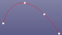
Interpolation points
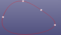
Check Closed option
Check Piecewise
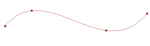
B-Spline without tangent constraint
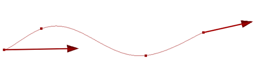
With tangent constraint
- On Surface
Create a B-spline curve on the surface by interpolation points locating at the same surface. It will automatically find the surface which the selected points locate at. You can create the point on the surface by using Geometry Tools, Project. If you want to close the B-spline curve on the surface, check Closed.
a. Only interpolation points
b. Interpolating curve on surface
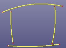
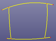
- Sketch on Mesh
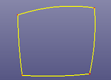
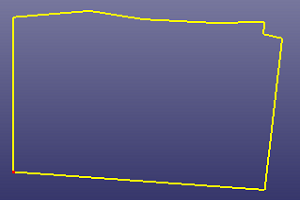
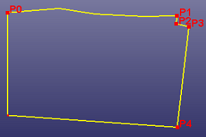
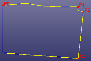
You can sketch curves directly onto mesh. Check Closed if the curve want to be closed. If you want to create one curve only, uncheck Multi-Curves. When Elastic on All Mesh is checked, the curve will be the convex hull of the sketched results.
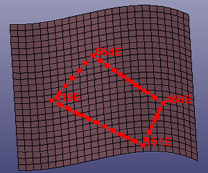
a. Sketch four corner points onto mesh
b. The final four sketched curves
c. Check Elastic on All Mesh and sketch two points
d. The final sketched curves
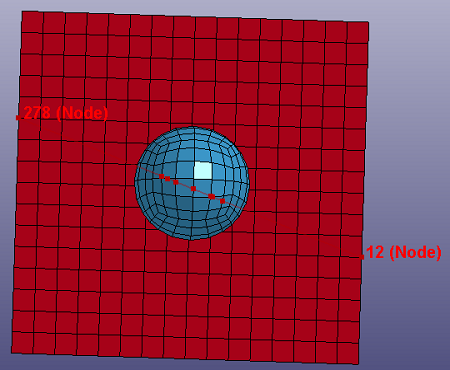
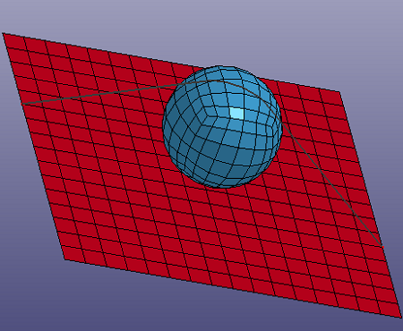
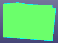
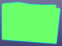
- From Mesh
Select Node, Part, Edge from shell elements. Especially, when you check "ByEdge" and "Prop" options, you can use angle tolerance to select multiple continuous edges by one click of the seed edge.
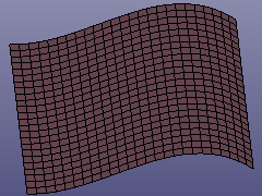
a. Raw shell
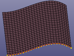
b. Curve from Mesh. See check option in figure c.
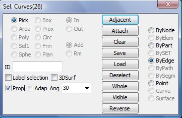
c. In gen. sel dialog, check "ByEdge", check "Prop", input "Ang" as 30.
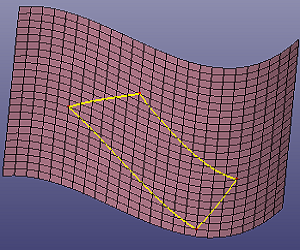
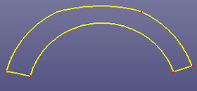
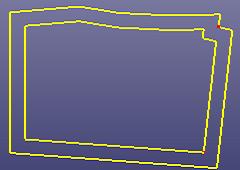
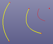
- Shell Intersection
Select shells to intersect with each other.
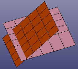
a. Two shells
b. Intersection curve of two shells (the yellow curve)
- Snap Edge End
Select independent edges to snap with each other. Internally the software projects each edge's end to a neighbour edge and move the end to the projecting position if the distance is under the given tolerance. If you don't know how to give a proper distance tolerance, you can go to GeomTools->Measure and select the vertex which you want to project and select the destination edge, there is a distance column in Measure dialog.
a. Raw curves
b. After snapping, By Extend is checked.
c. Using Trim->Mutual to trim edges, and delete the small curves
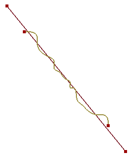
- Respace
To convert a curve to piecewise (one degree) b-spline curve, Respace will resample points and create a new curve. An advanced option of "Bias" is provided if you want to sample curve non-linearly. To sample points in specified direction, change Direction.
a. Raw curve
b. Respace By Number, num = 7
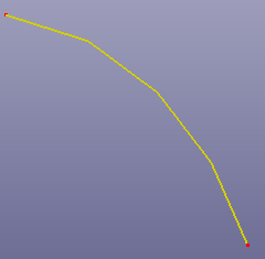
c. Respace By Number, num=5
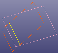
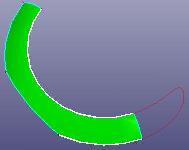
- Respace Para
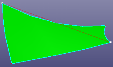
Project or map already spaced curves to unspaced curves. When "Projection" is checked, the points in spaced curve will project to unspaced curve. The unspaced curve will copy the spaced parameter from spaced curves when "Mapping" is checked.
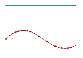
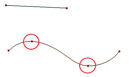
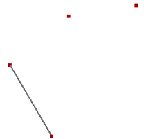
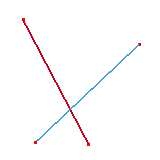
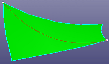
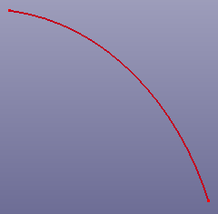
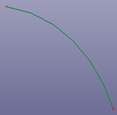
a. Raw curves. The green curve is a spaced curve. Respace the red curve by the green curve.
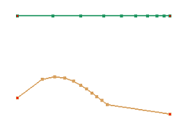
b. Respace result by Projection using Direction as Default
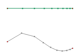
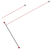
c. Respace result by Projection using Direct as "Y"
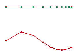
d. Respace result by Mapping
- Cur Map to Surf
Map curves to surface.
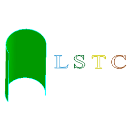
a. Raw curves "LSTC" and a cylinder surface
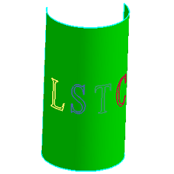
b. Map "LSTC" to surface. U scale is 0.6, V scale is 0.2
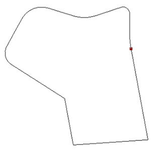
- From Mesh Hole
Search inner or outer boundaries from shell mesh and create b-spline curves using the boundary nodes.
- Plane's Medial Axis
Search inner medial axis from a planar face.

a. Raw planar face
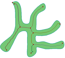
b. Medial axis extraction
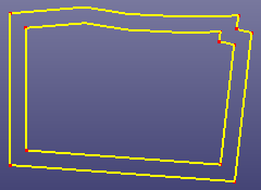
- Adjust Start Pnt
Adjust end point in a closed curve. "Reverse" is an option to reverse close curve's direction.

a. End point in raw closed curve
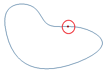
b. Curve after adjusting the end point
The helix can be used as a path or guide curve for a swept or loft feature. Click View, Geom Curve to toggle the display of individual curve.
To create a helix curve: Click Helix (Curve toolbar) or click Geometry, Curve, Helix.
There provides four types helix: Cylinder, Cone, Torus and Along Curve. To create a helix, select a coordinate system or circle, cylinder or cone firstly, define the radius next. If you select a circle or a cylinder, the radius will be automatically setting as the radius of the circle or cylinder. For Conical, Torus, Along Curve, you should define two radius. Helix types:
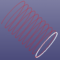
a. Cylindrical helix
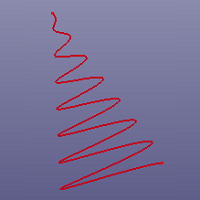
b. Conical helix
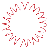
c. Torus helix
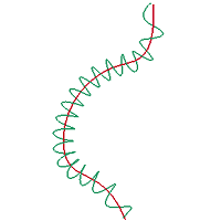
d. Along Curve
The other three parameters are loop number, height and total distance.
The Helix dialog has the following creating methods:
- Distance/Loop
Creates a helix defined by distance between each loop and loop number (the number of turns).
- Height/Loop
Creates a helix defined by the total height and loop number.
- Height/Distance
Creates a helix defined by total height and distance between each loop.
You can create composite curves (wire) by combining curves, and model edges into a single wire. Use a composite curve (wire) as a profile or path curve when creating a loft or a sweep.
To create a composite curve: Click Composite Curve (Curve toolbar) or click Geometry, Curve, Composite Curve.
In the dialog, select the type of you want to create the wire:
- Edge List
To create a composite curve into a single wire, select the edges in order. If the neighbour edge are not strictly connect with each other, check "End Constraint" to make them connected. Then you can use the wire to construct more complex shell/solid feature. If you click "Search", it will search neighbour edges automatically according to the highlight edges in the list box. If the raw edges in the list box are independent edges, when "Hide raw edge" is checked, they will be hide after creating wire.
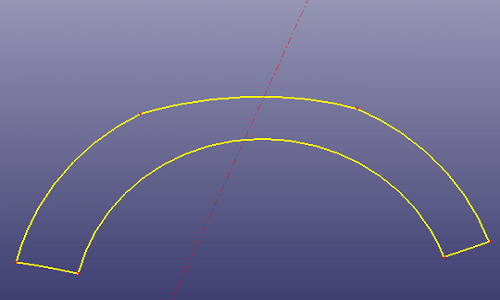
a. Create Composite Curve (Wire)
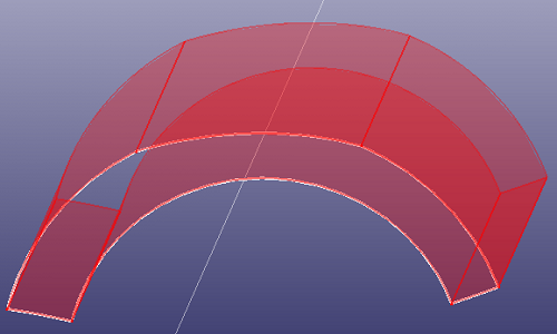
b. Create an Extrude feature(shell) using wire as profile
- Bounds of Shell
Select the shell, and create the wires out of the shell.
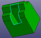
a. Shell has a boundary
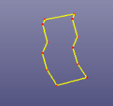
b. Extract boundary to wire
You can split curve into multiple sub curves by project points onto the curve.
To break a curve:Click Break Curve (Curve toolbar) or click Geometry, Curve, Break Curve.
In the dialog, select the curve break type:
- Auto
Select a curve, it will automatically search the break points on the curve according to angle and distance tolerance.
a. Raw curve
b. Searched point lists. "Max. Ang" sets as 60.0
c. Searched point lists. "Max. Ang" sets as 60.0 and check "Use Step Len"
- Manual
Select a curve and some break points on the curve. It will break curve manually.

a. Closed curve
b. Select five reference points to split curve
c. The final 6 curves split from raw curve
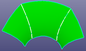
- Batch
Select one or more faces. It will automatically break the face boundaries according to angle tolerance.
a. Face has only one edge
b. Batch break face, "Max. Ang" set as 60.0
- Parameter
Using parameter to break curve. Suppose curve's parameter is [u0, u1], the input parameter is s, s in (0, 1.0). The mapping break parameter in curve will be u0+(u1-u0)*s. If N Segment is checked, the curve will be break uniformly by distance.
- Tangent Span
It will sample lots of points in the selected curve, and compare each point's tangent with its neighbor point's tangent. If the angle difference is less than a given value, the point will be chosen as a break point.
a. Raw curve
b. Tangent Span breaking result
You can merge neighbour curves into a single curve.
To merge curves: Click Merge Curve (Curve toolbar) or click Geometry, Curve, Merge Curve.
In the dialog, select the type of you want to merge curves:
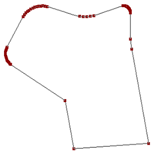
- Single
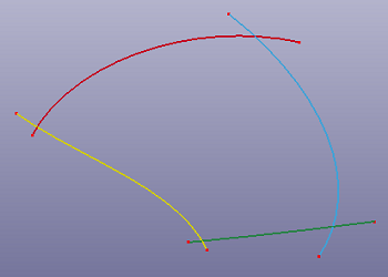
To merge several neighbour curves into a single curve, select the curves. In fact, it's not necessary to select curves in order, the Merge Curve will sort the curves automatically according to neighbour distance. If the merged curve is not smooth, check "Refitting" to refit the merged curve. If you want to merge curves to a polygon, check Piecewise.
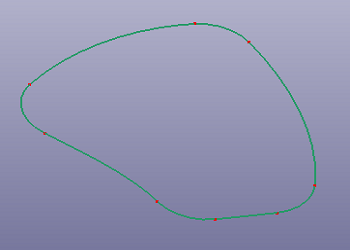
a. 6 neighbour curves
b. Merge into one single curve
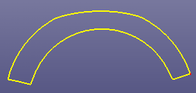
- Multiple
Merge curves into several B-spline curves according to gap tolerance. If the merged curves are not smooth, check "Refitting" to refit the merged curves.
a. Raw edges
b. Merge into two curves using "Multiple" method
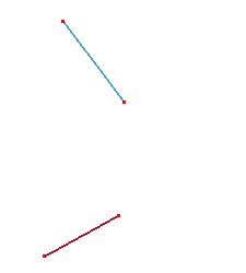
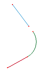
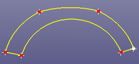
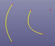
You can bridge two neighbour curves using Bridge Curve.
To bridge two curves: Click Bridge Curve (Curve toolbar) or click Geometry, Curve, Bridge Curve.
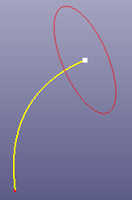
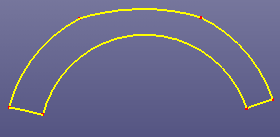
- 2 Curves
To bridge two curves naturally, select two curves and define the module length of the tangent directions properly. If two selected edges lay on the same surface, you can check "Same Surface" to constrain the new bridge curve on the surface. If you want the bridge curve's tangent module length is the same as the selected curve, check "Native Tan Module".
a. Bridge two curves on the same surface. Check "Same Surface"
b. Using the bridge curve to replace one edge on the surface (See Heal Model, Edge, Replace)
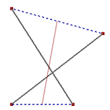
- 4 Points
You can also create a bridge curve by selecting four points. .
Bridge curve by 4 points
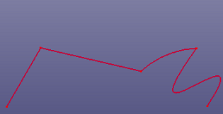
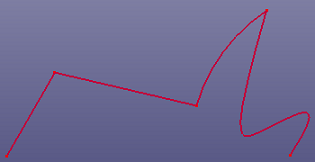
You can smooth noisy curve to make it properly used on surface/solid feature modeling.
To smooth curve: Click Smooth Curve (Curve toolbar) or click Geometry, Curve, Smooth Curve .
To smooth curve, select the curves and define the tolerance. If you want to create new curve, check "Copy" option.
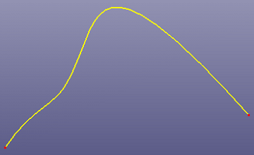
a. Noisy curve
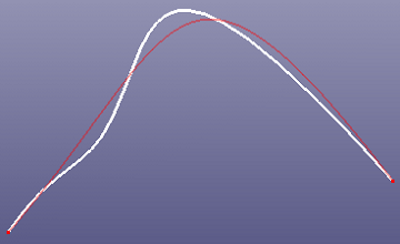
b. Smooth preview
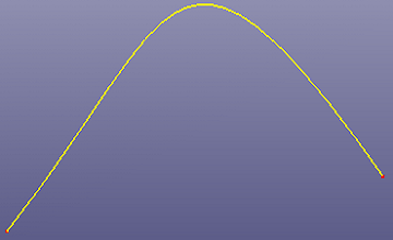
c. Final result
If selected multi-curves can be merged into one edge, you can check "Group Smooth" to smooth the merged curve. To smooth curve to piecewise b-spline curve, check "Polygon Smooth". When "Polygon Simplify Only" is checked, simplification method will be applied into smoothing.
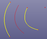
You can create a middle curve between two curves or points using Middle Curve. Furthermore, you can extract axis curves from pipe like shapes.
To create middle curve: Click Middle Curve (Curve toolbar) or click Geometry, Curve, Middle Curve.
- Middle Curve
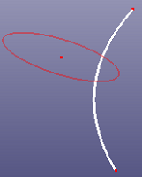
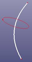
Middle curve locates between two selected curves. You can also create a middle curve between a curve and a point, or even create a middle point between two selected points. "Merge Wire to Edge" will firstly merge the selected curves into one curve.
a. Two source curves and one point.
b. Middle curve between two source curves.
c. Middle curve between one source curve and one source point.
- Axis of Pipe
Extract axis from pipe like shapes.
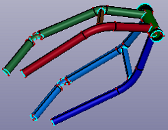
a. Source solid shapes
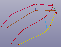
b. Axis of pipe
This command allows user to morph a curve to new position. There are 4 methods included in this dialog for curve morphing: curve morphing by segment, curve morphing by control point, curve morphing by curve point and global curve smooth.
The Morph dialog has the following creating methods:
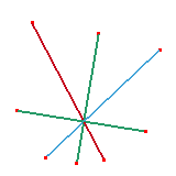
- Segment
Define a segment by selecting two points on the curve and morph this segment by picking one point.
- Selected curve:
Use General Selection Interface to select a curve, the ID number of this curve will show in the text field.
- Weighted smooth:
The segment is morphed by constraint of weighted smooth.
- Smooth:
The segment is morphed by constraint of general smooth.
- Linear:
The segment is morphed to be a polyline.
- WorkPlane(nx, ny, nz):
The plane with normal (dx, dy, dz) which the new segment locates on.
- Morphing direction(dx, dy, dz):
Enter the morphing direction vector (dx, dy, dz) in global coordinate.
- Distance:
The distance between the original picked point and the new morphed position.
- Reverse:
If this check box is checked, the morphing direction is reversed.
- Apply:
Add the morphed curve into database.
- Undo:
Undo segment morphing.
- Close:
Close this dialog.
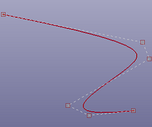
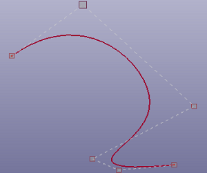
- Control Point
Select a curve, the control point of this curve will show, pick the control point to morph the curve.
- Selected curve:
Use General Selection Interface to select a curve, the ID number of this curve will show in the text field.
- Define direction(dx, dy, dz):
if this check box is checked, the three text fields will be activated. Enter a new morphing direction (dx, dy, dz) in global coordinate.
- Edit plane normal:
The edit plane is the plane which the picked control point locates on. Enter (nx, ny, nz) in global coordinate for the plane normal.
- Single:
Select single control point for curve morphing.
- Multiple:
Select multiple control points for curve morphing.
- Hide control points:
Check this check box to hide the control points
- Deselect:
Deselect a picked control point.
- Reset:
Reset the curve to be original position.
- Apply:
Add the morphed curve into database.
- Undo:
Undo curve morphing.
- Close:
Close the dialog.
- Curve Point
Select a curve, the curve points will show, pick the curve point to morph the curve.
- Selected curve:
Use General Selection Interface to select a curve, the ID number of this curve will show in the text field. After user selected a curve, curve points will show. User is allowed to pick the curve point and drag it to new position.
- Apply:
Add the morphed curve into database.
- Undo:
Undo curve morphing.
- Close:
Close the dialog.
- Global
Select a curve and smooth it by adjusting smoothness factor.
- Selected curve:
Use General Selection Interface to select a curve, the ID number of this curve will show in the text field.
- Smooth:
Use Position Dialog to get minimum/maximum point.
- Apply:
Enter target part ID.
- Undo:
Enter starting element ID.
- Close:
Enter starting node ID.
You can create fillet curves among several curves using Fillet Curve.
To create fillet curve: Click Fillet Curve (Curve toolbar) or click Geometry, Curve, Fillet Curve.
You can select edges or shared vertex to create fillets between two neighbour curves. Normally, all source curves should locate at the same plane. If selected edges are not strictly located in a plane, check "Project to Plane". "Try to Trim" is to trim curves mutually before fillet.
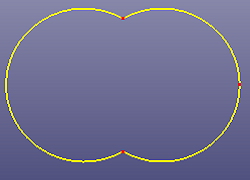
a. Two circles (radius=1.0) trimmed with each other
b. Create fillet curves between each circular arcs. The fillet radius is set as 0.7
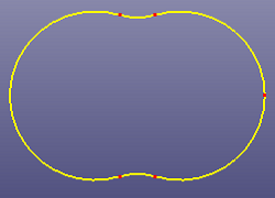
c. Four B-spline curves intersect with each other
d. Fillet results after checking Try to Trim
You can create curves by sketch. Click View, Geom Curve to toggle the display of individual curve.
To create sketch: Click Sketch (Curve toolbar) or click Geometry, Curve, Sketch.
In the dialog, select a sketch plane firstly. Next, choose the specified sketch type. Sketch types contain: Line, Circle, Rectangle, Arc, Conic Curves, Slot, B-spline Curve, Curve Cut, Transform, Delete, Configuration, Undo and Apply. You can input point's coordinates in U and V text control, and press Enter to input a sketch point. To input next point by angle and length relative to last point, enter values into "Angle" and "Length".
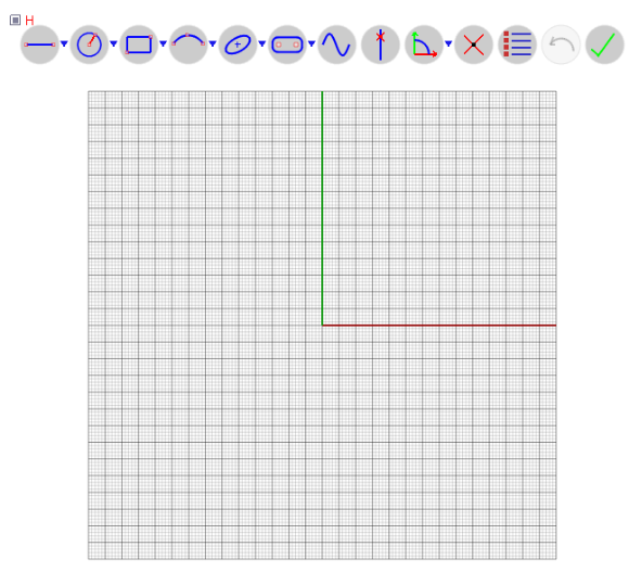
a. Sketch UI
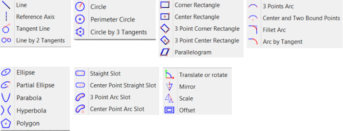
b. Sketch Types
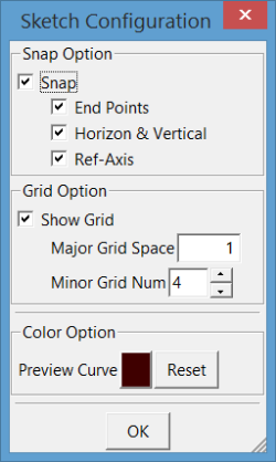
c. Sketch Configuration
You can convert curve to/from XYZ, IGES, STEP, DXF, VDA file. Convert curve to keyword.
To do a curve convert operation: Click Convert (Curve toolbar) or click Geometry, Curve, Convert.
In the dialog, select the type of you want to convert:
- To XYZ File
Convert the sampled points from the selected curves to XYZ file. You can use raw points in selected curves or resample points from curves by number or size. Check "LS_DYNA XYZ" to convert points to a DYNA XYZ file format. Convert points array from the selected curves to different files, check "Batch Exporting".
- From XYZ File
Convert XYZ points to piecewise b-spline curve. If the XYZ file is DYNA XYZ format, check "LS_DYNA XYZ". Load the points from the XYZ file but don't make B-Spline curve, check "Only to Points". If the point only contains X and Y component in the XYZ file, check "2D Point Format". "Check Duplicate" will remove neighbor duplicated points. "Piecewise" is an option to make points into one degree B-Spline curve or fit points to high degree B-Spline curve.
- To IGES/STEP
Convert the selected edges or all edges to IGES/STEP file. There are three types of edges: independent edge, edge in wire, and edge in face. "Show Only" write shown edges only.
- From IGES/STEP
Load edges from IGES/STEP file. There are three types edges in IGES/STEP file: independent edge, edge in wire, and edge in face.
- To Keyword
Convert the selected edges to keyword *DEFINE_CURVE_TRIM_3D, *DEFINE_TARGET_BOUNDARY, and *DEFINE_CURVE.
- From Keyword
Load curves from keyword *DEFINE_CURVE_TRIM_3D and *DEFINE_TARGET_BOUNDARY.
- To DXF/VDA
Convert sampled points from the selected curves to DXF/VDA file. You can use raw points in selected curves or resample points from curves by number or size. Convert every selected curve to a file, check "Batch Exporting".
- From VDA
Convert points in VDA file to piecewise b-spline curve or line segments.
- To SketchBoard
Convert 2d curves to sketch board.
You can create parabola by several construction types. Click View, Geom Curve to toggle the display of individual curve.
To create a parabola: Click Parabola (Curve toolbar) or click Geometry, Curve, Parabola.
In the dialog, select the type of you want to create the parabola:
- Parameters
Create parabola by center, normal, start direction, focal, start and end parameters.
- Point/Axis
Create parabola by selecting a point, an axis and define the start and end parameters.
- Coordinate System
Create parabola by selecting a coordinate system, and define the focal, start and end parameters.
You can create hyperbola by several construction types. Click View, Geom Curve to toggle the display of individual curve.
To create a hyperbola: Click Hyperbola (Curve toolbar) or click Geometry, Curve, Hyperbola.
In the dialog, select the type of you want to create the hyperbola:
- Parameters
Create hyperbola by center, normal, start direction, major and minor radius, start and end parameters.
- Coordinate System
Create hyperbola by selecting a coordinate system, and define the major and minor radius, start and end parameters.
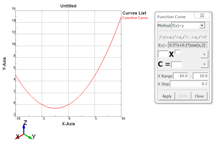
You can create any parameter curves by defining proper function parameters. The result is a one degree B-Spline curve. Click View, Geom Curve to toggle the display of individual curve.
To create a function curve: Click Function (Curve toolbar) or click Geometry, Curve, Function.
In the dialog, select the type of you want to create the function curve:
- f(x)=y
The curve is defined as polynomial.
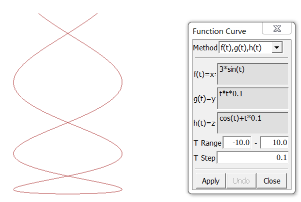
- x=f(t), y=g(t), z=h(t)
Parameter curve defined by x=f(t), y=g(t), z=h(t).
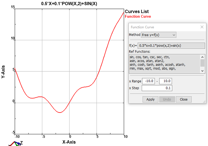
- Free y=f(x)
Here you can write C like formulae to define curve.
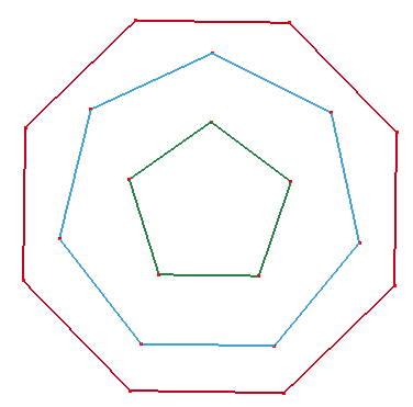
You can create any regular polygon by defining polygon's side number and side length or center length.. Click View, Geom Curve to toggle the display of individual curve.
To create a function curve: Click Polygon (Curve toolbar) or click Geometry, Curve, Polygon.
In the dialog, define the side number and side length or check "Center Length" to define center length. If you want the polygon to be a single piecewise b-spline curve, check "Single Curve". You can also sketch polygons onto plane by checking "Sketch on Plane".
In curve fit dialog, you can fit point, line, circle, ellipse, hyperbola, parabola and B-Spline curve.
To fit a primary curve: Click Fit (Curve toolbar) or click Geometry, Curve, Fit.
In the dialog, select points or curves from model, click the specified curve type to fit a curve.
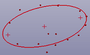
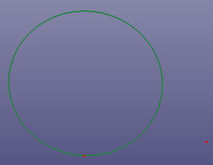
a. Fit ellipse
b. Fit B-Spline curve