Solid is the final geometry type of the CAD modeling. It's usually a closed shape which contains lots of faces which stitch together. Solid tools are available on the Solid toolbar. You can create or modify solid by these methods:
- Box
From a coordinate system and define the length and width, or create by two points.
- Cylinder
From a coordinate system and define the radius, start/end angle, and start/end height, or create by specifying bottom, top center.
- Cone
From a coordinate system, and define the top/bottom radius, start/end angle and start/end height, or create by specifying bottom, top center and radius.
- Sphere
From a coordinate system, and define the radius and u/v start/end angles, or create by select center point and another point on sphere or define the radius.
- Torus
From a coordinate system and define the path and profile radius, and other three angles parameters.
- Extrude
Given a face as profile, an axis as direction, it linearly extrudes to a solid.
- Revolve
Given a face as profile, an axis as rotational direction, it rotates to a solid.
- Sweep
Given a face as profile, an edge or wire as path curve, it sweeps to a solid.
- Loft
Give a set of closed edges or wires, it loft a solid. The two ends of the curves group can be replace by point. Such as you can create a cone solid by loft a circle and a point.
- Fillet
Fillet creates a rounded internal or external face on the part. You can fillet all edges of a face, selected sets of faces, selected edges, or edge loops.
- Chamfer
The chamfer tool creates a beveled feature on selected edges, faces.
- Draft
Draft tapers faces using a specified angle to selected faces in the model. One application is to make a molded part easier to remove from the mold. You can insert a draft in an existing part or draft while extruding a feature. You can apply draft to solid or surface models.
- Thicken
Creates a solid feature by thickening one or more adjacent surfaces.
- Wedge
Wedge tool support to build wedges, that is, boxes with inclined faces.
- Boolean
Boolean operation contains cut, common, and fuse two solid shapes.
- Prism
Create prism, pyramid or draft shape by side number, side length, height and other parameters.
- Combine
Given two profiles and two extrusion direction, it will calculate the boolean-intersection solid shape.
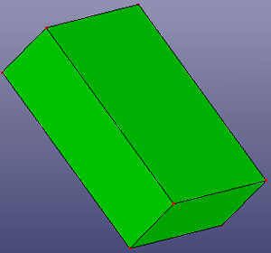
You can create a solid box by parameters, 2 points, or entities' bounding box.
To create a box, Click Box(Solid toolbar) or click Geometry->Solid->Box.
In the dialog, select the type of you want to create the box:
- Parameters
Create a box by parameters. The parameters contain a local coordinate system, start and end X, Y, Z coordinates on the local coordinate system. By default, the coordinate system is set as the standard global coordinate system.
By parameters
- Two Points
Create a box by two points which locate at two corners.
By 2 points
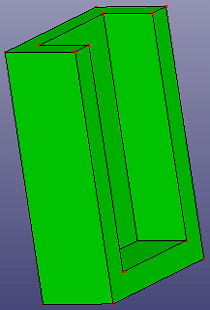
- BoundBox
Create a box originally from a bounding box of selected items. Four options are "By Shapes", "By FEM", "By Assembly", and "Whole Model".
"OBB" is the oriented bounding box of the selected shapes. This box is usually treated as the minimum bounding box.
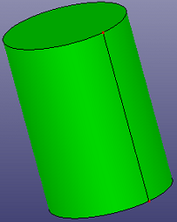
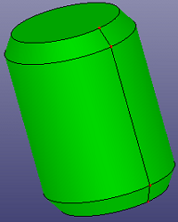
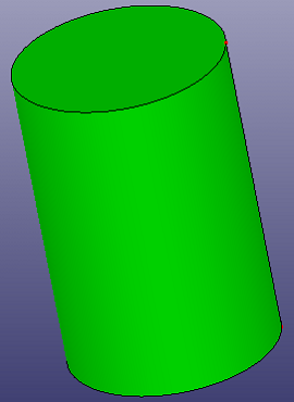
You can create a cylinder solid by parameters or by two points.
To create a cylinder: Click Cylinder(Solid toolbar) or click Geometry, Solid, Cylinder.
In the dialog, select the type of you want to create the cylinder:
- Parameters
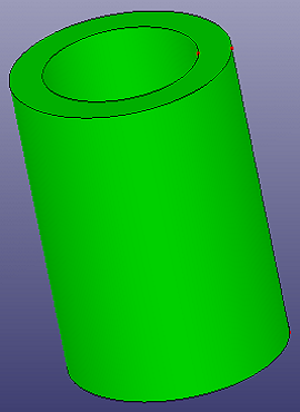
Create a cylinder by parameters. The parameters contain a local coordinate system, start/end angles, and start/end heights. By default, the coordinate system is set as the standard global coordinate system.
By parameters
- Bot/Top Pnt
Select two points as the bottom and top center of the cylinder. And define the radius, start and end angle.
By 2 points
You can create a cone solid by parameters or by bottom/top centers.
To create a cone: Click Cone(Solid toolbar) or click Geometry, Solid, Cone.
In the dialog, select the type of you want to create the cone:
- Parameters
Create a cone by parameters. The parameters contains:
A local coordinate system. By default, it is set as the global standard coordinate stem.
Bottom and top radius.
Start/end height.
Start/end Angle
By parameters
- Bot/Top Pnt
Select two points as the bottom and top center of the cone. And define the bottom and top radius, and start/end angle.
By bottom and top center
You can create a solid sphere by parameters or by center point.
To create a sphere: Click Sphere(Solid toolbar) or click Geometry, Solid, Sphere.
In the dialog, select the type of you want to create the sphere:
- Parameters
Create a sphere by parameters. The parameters contains:
A local coordinate system. By default, it is set as the global standard coordinate system.
Radius
U start/end angle. Input angle between -90.0 ~ 90.0.
V span angle. Input angle between 0.0 ~ 360.0.
By parameters
- Center Point
Select a point as the center of the sphere. Select another point as the point on the surface or define the radius directly.
By center point
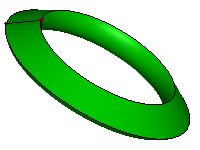
You can create a torus solid by parameters.
To create a torus: Click Torus (Solid toolbar) or click Geometry, Solid, Torus.
To create a torus, using following parameters:
A local coordinate system. By default, it is set as the global standard coordinate system.
Path radius.
Profile radius.
U start/end angle. Input angle between -180.0 ~ 180.0.
V start/end angle between 0.0 ~ 360.0.
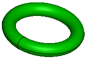
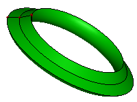
For partial torus shape, here provides three filling method:
Default Fill
Half Fill
Detail Fill
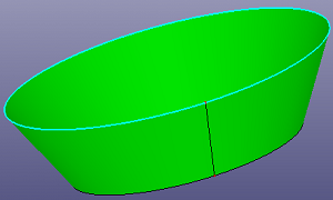
You can create an extruded solid by a profile face and a direction.
To create an extruded solid: Click Extrude (Solid toolbar) or click Geometry, Solid, Extrude.
To extrude a face, by following method:
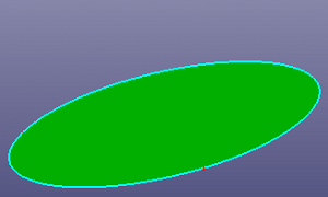
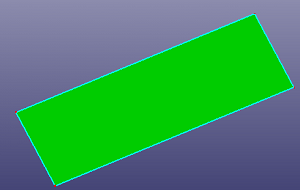
Profile Shape. Select a face as the profile.
Extrude Direction. Select an axis or a line shape as the direction. If the profile face is planar, the default direction is the normal of the plan which profile curve locates.
Start and End Distance. Define the profile's start and end position.
If the profile locates in the middle of the solid, check "Both Symmetric" to build symmetric extrude solid shape.
Plane profile.
Extrude Solid
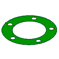
You can create a revolve solid by a profile face and an axis.
To create a revolve solid: Click Revolve (Solid toolbar) or click Geometry, Solid, Revolve.
To create a revolve solid, by following method:
Profile Shape. Select a face as the profile.
Revolve Axis. Select an axis or a line shape as the axis.
Start and End Angle. Define the profile's start and end position.
Plane profile and an axis.
Revolve Solid
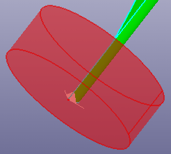
You can create a sweep solid by a profile face and a path curve.
To open sweep solid: Click Sweep (Solid toolbar) or click Geometry, Solid, Sweep.
To create a sweep solid, select a face as profile and select an edge or wire as path curve.
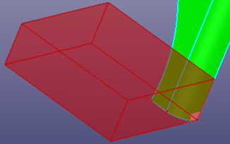
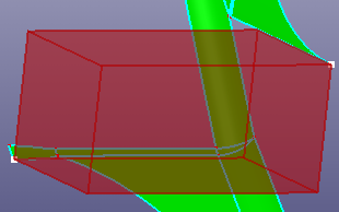
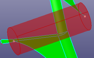
If you want to move path curve's end to nearest point in the profile face, check "End Constraint", and the path curve will automatically translate to profile.
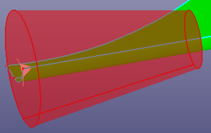
If the path curve is noisy, you can also check "Smooth Path" to make the path smooth.
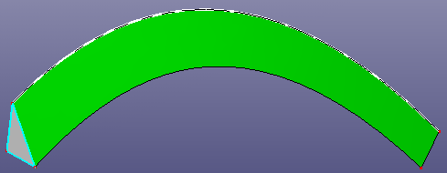
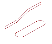
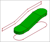
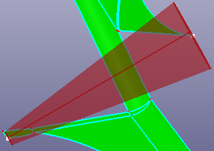
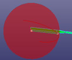
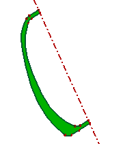
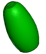
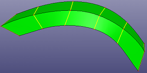
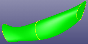
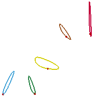
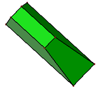
Solid sweep: A triangle face as profile, a B-spline curve as path curve
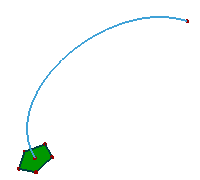
a. A profile face and a path curve
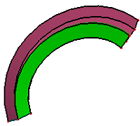
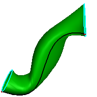
b. Normal result (green) and "End Constraint" result (pink)
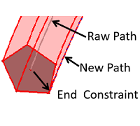
c. "End Constraint" method
Loft is a solid passing through a set of closed sections in a given sequence. Usually sections are edges or wires, but the first and the last sections may be vertices (punctual sections).
To open loft solid: Click Loft (Solid toolbar) or click Geometry, Solid, Loft.
To create a loft solid, select a set of sections in a given sequence. Usually sections are closed edges or wires, but the first and the last sections may be vertices. To make the solid closed, check "Closed" to make the final section is the same with the first section. When selecting profile, there are a serial guided points to show, the guided points match two neighbour profile curves's end points' direction.
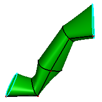
Using 6 closed wires as profile to make a solid loft operation
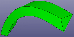
Using 3 closed curves as profile to make a solid loft operation
To linear interpolate between neighbor profiles, check "Ruled" option.
a. 5 closed profile curves
b. Loft result without "Ruled"
c. Loft result using "Ruled"
Fillet creates a rounded internal or external face on the shell or solid shape. You can fillet all edges of a face, selected sets of faces, selected edges, or edge loops.
To open fillet: Click Fillet (Solid toolbar) or click Geometry, Solid, Fillet.
Recommendations for Fillets:
In general, it is best to follow these rules when making fillets:
Add larger fillets before smaller ones. When several fillets converge at a vertex, create the larger fillets first.
Add drafts before fillets. If you are creating a molded or cast part with many filleted edges and drafted surfaces, in most cases you should add the draft features before the fillets.
Save cosmetic fillets for last. Try to add cosmetic fillets after most other geometry is in place. If you add them earlier, it takes longer to rebuild the part.
To enable a part to rebuild more rapidly, use a single Fillet operation to treat several edges that require equal radius fillets. However, if you change the radius of that fillet, all the fillets created in the same operation change.
To make a fillet operation,
Select fillet type: equal radius or various radius.
Select edges or faces from a shell or a solid.
a. raw solid
b. constant radius fillet
a. raw solid
b. various radius fillet
The chamfer tool creates a beveled feature on selected edges, or faces.
To open chamfer: Click Chamfer (Solid toolbar) or click Geometry, Solid, Chamfer.
To create a chamfer, select chamfer type: Angle-Distance, Distance-Distance. Then select an entity in the graphics area for Edges or Faces.
You can check "Reverse" to reverse the chamfer's reference direction.
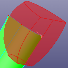
a. raw solid
b. chamfer result
Draft tapers faces using a specified angle to selected faces in the model. One application is to make a molded part easier to remove from the mold. You can insert a draft in an existing part or draft while extruding a feature. You can apply draft to solid or surface models.
To open draft: Click Draft (Solid toolbar) or click Geometry, Solid, Draft.
To make a draft,
Select wire, face or shell which has open boundary.
Select the draft direction.
Define the draft angle and maximum length.
Check option "Internal Draft", "Round Corner" or "Reverse Direction".
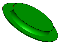
a. raw face
b. draft result
a. raw face
b. draft result
Solid Thicken is to creates a solid feature by thickening one or more adjacent surfaces on shell or solid. If the surface you want to thicken is comprised of multiple adjacent surfaces, you must first knit the surfaces together before you thicken the surface.
To open thicken: Click Thicken (Solid toolbar) or click Geometry, Solid, Thicken.
To make a thicken operation,
Select shell or shell to be thicken.
Select faces from the shell or solid which should be delete when thicken.
Define the thickness and tolerance.
a. raw solid
b. delete top face and thicken
a. raw solid
b. delete top and side faces and thicken
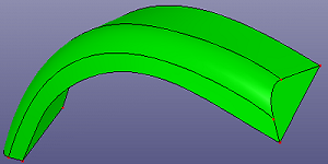
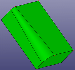
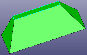
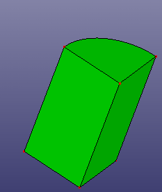
Solid wedge tool support to build wedges, that is, boxes with inclined faces.
To open wedge: Click Wedge (Solid toolbar) or click Geometry, Solid, Wedge.
To create a wedge,
Select a coordinate system. The default coordinate system is the global standard coordinate system.
Define the wedge's length, width and height.
Define the min, max X and Z's coordinates.
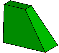
a. wedge side view
b. wedge top view
Boolean operation contains cut, common, and fuse which operate on two solid shapes.
To open boolean: Click Boolean (Solid toolbar) or click Geometry, Solid, Boolean.
To make a boolean operation,
Select two or more solid shapes.
Select boolean operation type: Union, Sub, and Common.
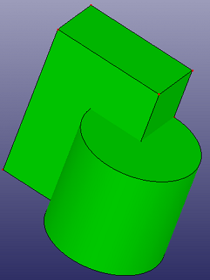
a. raw two solids
b. union result
c. sub result
b. common result
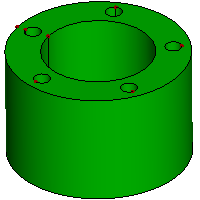
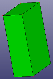
You can create a solid prism, pyramid, and draft in Solid Prism.
To create a prism: Click Prism(Solid toolbar) or click Geometry, Solid, Prism .
In the dialog, select the type of you want to create:
Prism. Using side length, side number and height to define a solid prism.
Pyramid. Using side length, side number and height to define a solid pyramid.
Draft. Using side length, side number, height and draft angle to define a solid pyramid.
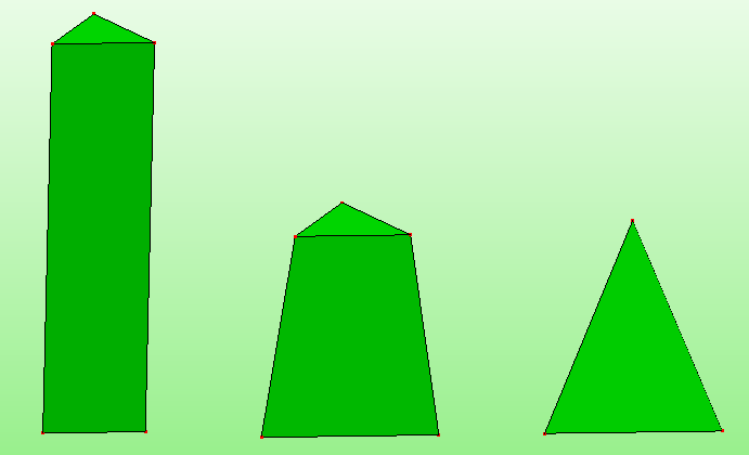
Solid prism, draft, and pyramid
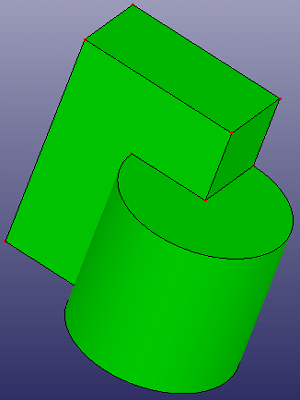
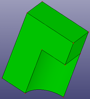
Given two profiles and two extrude direction, calculate the intersection shape.
To create a combine: Click Combine (Solid toolbar) or click Geometry, Solid, Combine.
In the dialog, select two profiles and define two extrude direction.
Combine operation equals to two solid extrude operations, plus one solid boolean intersection operation.