


It contains several advanced geometry modify tools. Geometry tools are available on the Geometry Tools toolbar. You can modify geometry and topology by these methods:
- Delete Entity
Delete any geometry related entity or faces from shell, solid, and you can also repair or fill the gap of the hole after deleting.
- Blank Entity
Blank any geometry related entity.
- Extend Curve
Extend curve by selecting a vertex or a curve.
- Extend Face
Extend a surface by selecting an edge, multiple edges, or a face.
- Intersection
Get intersection by selecting edges or faces.
- Offset
Offset by existing faces or surfaces, or by planar edge or wire, or by edge on face.
- Project
Project vertex, edge or wire onto face or shell.
- Replace Face/Search
Replace old faces with a new face, it's similar with deleting old faces and stitching the new face to the left faces. You can also search similar shapes by source shape.
- Stitch Faces
Sew neighbour faces together to make a whole shell or solid, and the neighbour face will share the same edges.
- Trim
Use a vertex, edge, wire or face as a trim tool to trim edge, wire or face. You can also use a face in conjunction with additional faces, as mutual trim tools.
- Transform
Translate, rotate, mirror or scale shapes by transform tool.
- Reverse Direction
Reverse edge,wire, face, shell or solid's direction.
- Copy
Copy entities.
- Management
List all shapes' ID, and you can also blank, delete shapes, export shapes to IGES or step file, clean all shapes from the model, or split all shell/solids into independent faces.
- Heal
Heal the problem on face, edge, vertex and hole.
- Simplify
Untrim face, remove inner hole, search and remove fillet surface/edge, reshape edge.
- Measure
Show shapes' ID, measure shapes' geometry information or neighbour relationship.
- Text Object
Create text object to curve, surface or solid shape.
- Array Flow
Transform shapes by align, array, flow, shear and twist.
The tool supports deleting any geometry related entity or dependent faces from shell or solid. There provide two options: Any and Face. In Any mode, you can delete any shape, delete blank shapes, remove whole model or clear specified types' shapes. In Face mode, you can also repair or fill the gap on the shell or solid.
To open Delete Entity, click Delete Entity (Geometry Tools toolbar) or click Geometry, Geometry Tools, Delete Entity.
In the dialog, there are two options: Any and Face.
In Any mode, you can delete any geometry related entities including ref-geoms and shapes. To clear specified types of entities, check specified filters and click "Clear". To delete all blank shapes, click button "Remove Blank". To delete an unshared vertex from a face, check "Repair Mode". To replace a complex edge from face with a simple edge, check "Repair Mode".
a. Raw face
b. Under "Repair Mode", delete two vertices
c. Under "Repair Mode", delete a complex edge
In Face mode, select the type of you want to delete face:
- Delete
Delete the independent faces or dependent faces from shell/solid directly.
- Delete and Repair
Delete dependent faces from shell/solid, and try to extend neighbor faces and trim with each other.
- Delete and Fill
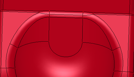
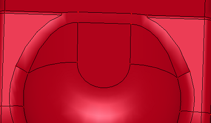
Delete dependent faces from shell/solid, and fill the gap with a N-side surface.
- Delete and Simple Fill
Delete dependent faces from shell/solid, and try to fill the gap. It's similar with Delete and Fill, but using different filling method.
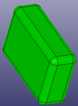
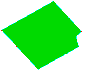
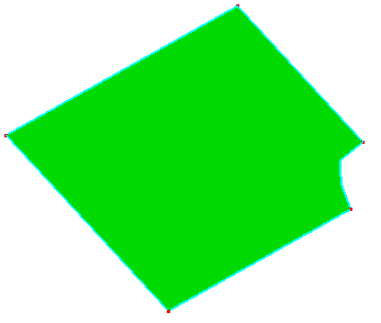
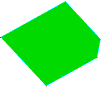
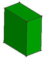
a. Solid box
b. Delete
c. Delete and Repair
d. Delete and Fill
Use Blank Entity to blank any geometry entity.
To open Blank Entity: Click Blank Entity (Geometry Tools toolbar) or click Geometry, Geometry Tools, Blank Entity .
In the dialog, you can blank specified types of entities by checking related filters. You can also blank/unblank all and reverse blank. When "Blank Independent" is checked, the independent shape will be blank. Such as selecting one face from a solid, the solid will be blank.
If a face has been meshed, you can blank/show those kind of faces by "Meshed Face" option.
Blank All. Blank all geometry related entities in current model.
Unblank All. Unblank all geometry related entities in current model.
Reverse. Reverse blank all geometry related entities in current model.
Undo Last. Undo last blank operation.
You can extend a curve by selecting an vertex on the edge, or an edge.
To open Extend Curve: Click Extend Curve (Geometry Tools toolbar) or click Geometry, Geometry Tools, Extend Curve.
In the dialog, select the type you want to extend curve:
1. Select the Stop Condition
Distance. Extends the curve by the value you specify in Length.
Up to face. Extends the curve to the face selected in the graphics area for Face.
Up to edge. Extends the curve to the edge selected in the graphics area for Edge.
Up to vertex. Extends the curve to the vertex selected in the graphics area for Vertex.
2. Select the extension type
Linear. Extends the curve along the tangent direction in the original vertex on the curve.
Same Curve. Extends the curve along the geometry of the curve. Such as circular arc extends along the circle, elliptical arc extends along the ellipse.
Extend on Face. Extends the curve on the face if the curve locates on any face.
a. Extend both ends
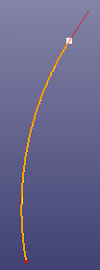
b. Extend on end
c. Extend to face
d. Extend to face
e. Extend linearly
f. Extend at trim curve(Same Curve)
g. Curve on surface
h. Extend curve linearly
i. Extend curve linearly at the surface (Extend on face)
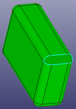
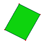
You can extend a face by selecting edges on the face, or a face.
To open Extend Face: Click Extend Face (Geometry Tools toolbar) or click Geometry, Geometry Tools, Extend Face.
In the dialog, select the type you want to extend face:
- 1. Select the Stop Condition
Distance. Extends the face by the value you specify in Length.
Up to surface. Extends the face to the face selected in the graphics area for Face. In this mode, you can also check Offset by Distance, it will use offset method to check extend distance.
Up to vertex. Extends the face to the vertex selected in the graphics area for Vertex.
- 2. Select the extension type
Linear. Extends the face tangent to the original face along the edges.
Same Surface. Extends the face along the geometry of the face.
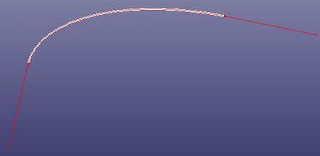
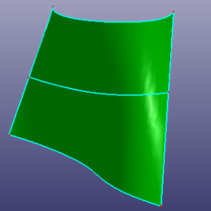
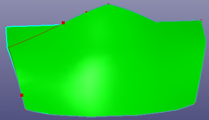
a. Extend surface by selecting two edges
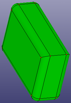
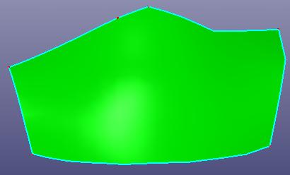
b. Extend surface by selecting face
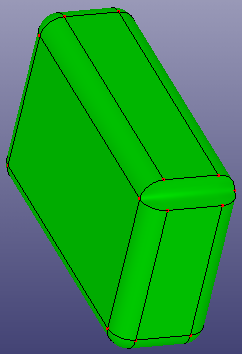
c. Preview of extending surface to the selected vertex
d. Result of extend surface to vertex
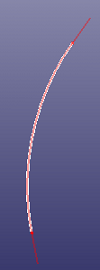
e. Extend surface linearly
You can select edge or face to calculate the intersection point or curve.
To open Intersection: Click Intersection (Geometry Tools toolbar) or click Geometry, Geometry Tools, Intersection.
In the dialog, select the type you want to intersect:
- Standard
Select edges, faces into group 1, select other edges, faces into group 2. The shapes in groups 1 will intersect with the shapes in group 2.
- Mutual
Select edges, faces into the group, and the shapes intersect with each other in the group.
a. Preview of intersecting
b. Intersecting results
There also provides two options: Relax Tolerance and Untrim Mode. When Relax Tolerance is checked, two unintersected shapes but locate very close can get the intersection. If Untrim Mode is checked, all selected shapes will be untrimmed firstly, and try to get intersection using the untrimmed curve, surface.
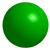
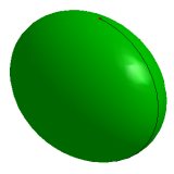
You can offset a face/shell, a planar edge/wire, or an edge on the face.
To open Offset: Click Offset (Geometry Tools toolbar) or click Geometry, Geometry Tools, Offset.
In the dialog, select the type you want to offset:
- Face/Shell
Select face or shell, define the offset distance, and give the round corner option. When "Offset to Solid" is checked, it will try to offset the faces to solid shape. Reverse offset direction, check "Reverse". Check "Offset to Solid" to make face offset to a solid shape. If you want to offset faces independently from shell/solid, check "Face Independent".
- Planar Edge/Wire
Select planar edge or wire, and define the offset distance. The result edge/wire will locate at the same plane. Reverse offset direction, check "Reverse".
- Edge on Face
Select edges from face, and define the offset distance. The result edge will locate at the same surface. Reverse offset direction, check "Reverse". Try to trim offset edges, check "Offset and Trim".
a. Raw face
b. Offset face to two directions (Face/Shell)
c. Offset face to Solid (Face/Shell, check "Offset to Solid")
a. Offset using Planar Edge/Wire
b. Offset using Edge on Face
Given a direction, you can project vertex, edge or wire to a destination face or shell.
To open Project: Click Project (Geometry Tools toolbar) or click Geometry, Geometry Tools, Project.
To project:
Select the destination face, shell or solid.
Select vertex, edge or wire to project.
Choose the project type:
- Normal Proj
This is a cylindrical projection. Select the projection direction. By default, if you don't specify any line or axis in Direction, it firstly tests whether the destination object is planar. If it is, by default the direction is set as the normal of the plane. Otherwise, it tests whether the selected edge or wire is planar shape, if it is, the plane normal is set as the projection direction.
- Conical Proj
Select the conical vertex as the view point.
- Closest Proj
It will automatically project source shape to destination shape by min distance projection.
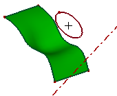
a. Projecting a circle onto a surface plane, direction is the red axis (Normal Projection)
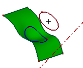
b. Projecting result
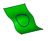
c. Projecting result (back view)
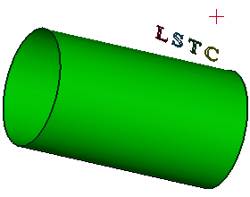
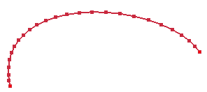
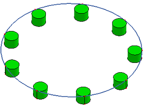
a. Select the ref-point (red) as the view point, project the curves "LSTC" loop to the cylinder. (Conical Projection)
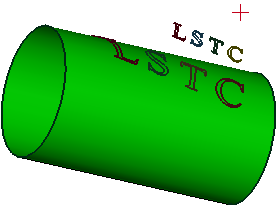
b. Projecting result
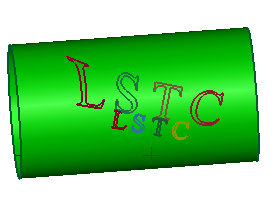
c. Projecting result (top view)
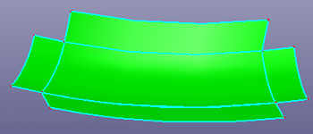
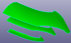
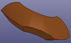
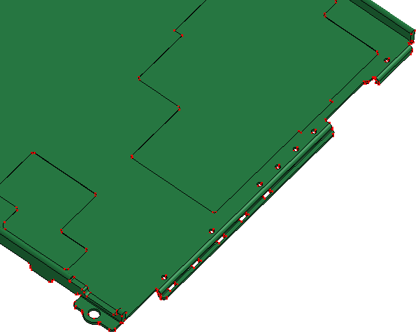
You can replace raw faces from a shell or solid by other new faces. And search similar shape by selected source shape.
To open Replace Face/Search Shape: Click Replace Face/Search Shape (Geometry Tools toolbar) or click Geometry, Geometry Tools, Replace Face/Search Shape.
To replace faces:
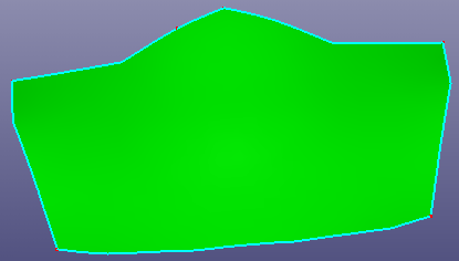
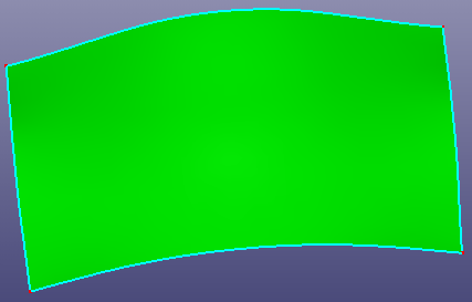
1. Select the raw faces from the same shell or solid.
2. Select the new faces to fill the gap of the raw faces removed.
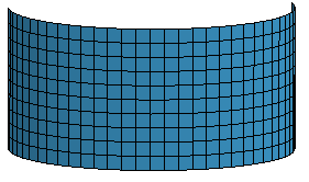
a. Raw shell
b. Replace middle several faces using a surface.
To search similar shape, select the source shape firstly(such as curve, surface), then click "Search", you can save the searched results to General Selection Buffer by clicking "ToSelBuf". If you want to make the selected source shapes as independent searching unit, you can check "Group Search".
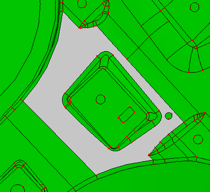
a. Select one source face
b. Searched similar faces.
To open Stitch Faces: Click Stitch Faces(Geometry Tools toolbar) or click Geometry, Geometry Tools, Stitch Faces.
To stitch faces, check Stitch:
Select the faces or check "All faces" to select all faces from current model.
If the faces can group into a shell which has no open bound, you can check "Try to make solid" to make the final shell into a solid.
Specify distance tolerance. It will be automatically calculated according to the bounding box of the selecting faces.
To stitch non-manifold model, you should check "Non-manifold Mode". Default it is unchecked.
To stitch the selecting face into several groups classified by the part ID, check "Group by part".
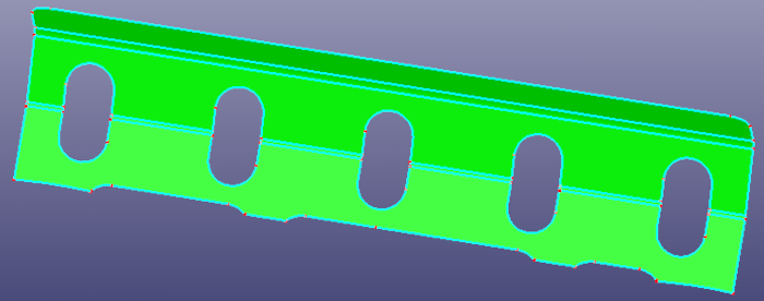
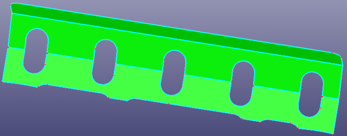
a. Raw independent faces
b. Shell after stitching
To decompose solid, check Decompose:
Select the shell or solid to Solid List.
To decompose shell or solid into independent faces, directly click "Apply".
To decompose non-manifold solid into manifold solids, check "Decom Non-Manifold".
a. Raw non-manifold solid (Notice: the pink colored edges are non-manifold edges)
b. Decompose raw solid into 4 manifold solids
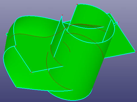
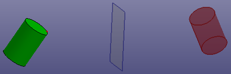
You can use vertex, edge, wire or face to trim edge, wire or face. You can also use a face in conjunction with additional surfaces, as mutual trim tools.
To open Trim: Click Trim(Geometry Tools toolbar) or click Geometry, Geometry Tools, Trim.
Under Trim Type, select a type:
- Standard
Trims edge, wire or face using vertex, edge, wire, or face. Vertex can trim edge or wire only. If the trim tool shape is not large enough, you can check "Raw Trim Tool" to recover a large trim tool shape. If the trim tool is an edge, you can also check "Extrude Edge Tool" to make the edge trim tool as a extrude face trim tool.
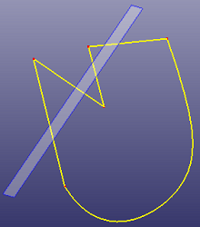
a. Using ref-plane as trim tool to trim the wire (Standard)
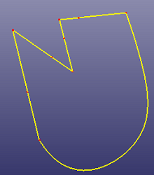
b. The final wire after trimming
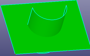
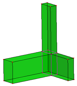
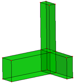
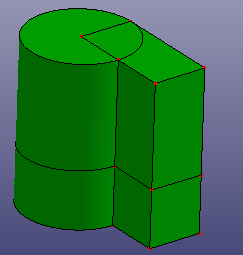
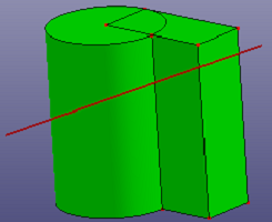
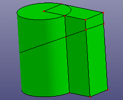
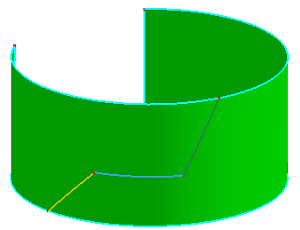
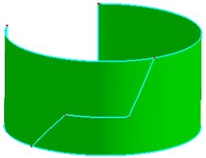
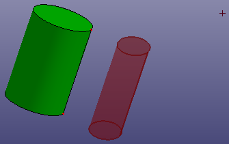
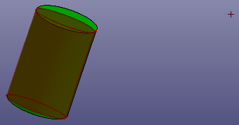
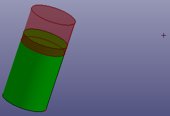
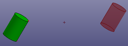
a. Using a face as trim tool to trim the cylinder (Standard)
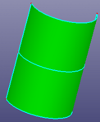
b. The two sub cylinder faces after trimming
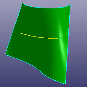
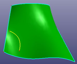
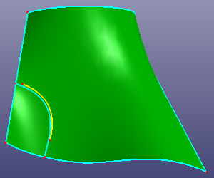
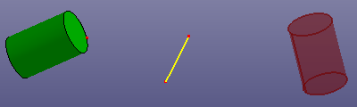
a. Use the yellow edge as the trim tool to trim the face (Standard), the edge is on the face but not large enough to cross the face boundary
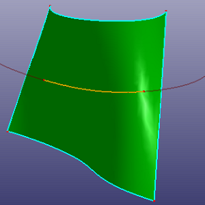
b. Check "Raw Trim Tool" to make this edge large enough to cross face boundary
c. Results after trimming
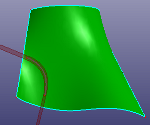
a. Use the yellow edge as the trim tool to trim the face (Standard), the edge is NOT on the face and not large enough to cross the face boundary
b. Side view
c. Check "Raw Trim Tool" and "Extrude Edge Tool" to make this edge large enough to cross face boundary
d. Results after trimming
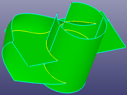
- Mutual
Trims faces or edges with each other in the list box.
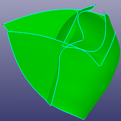
a. Four faces to trim with each other (Mutual)
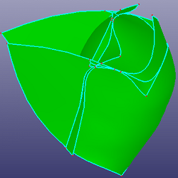
b. Results after trimming
c. Results after deleting the small faces
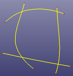
a. Four curves to trim with each other (Mutual)
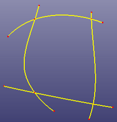
b. Results after trimming
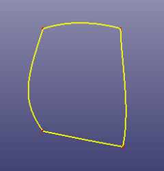
c. Results after deleting the small edges
- Cut Solid
Cut a solid shape by a ref-plane or any face. If the selected face is not totally cross the solid, you can check "Raw Trim Tool" to recover a large trim tool face. If you want to use a sketched plane to cut the solid, you can also check "Sketch Section Plane" to sketch temporary plane directly as the trim tool.
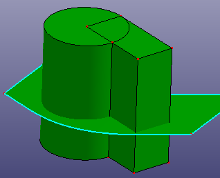
a. Select a face to cut a solid (Cut Solid)
b. Results after trimming
a. Sketch a section plane to cut solid (Cut Solid)
b. Results after trimming
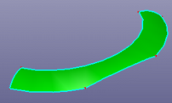
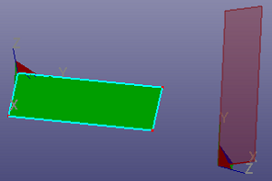
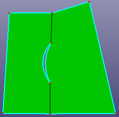
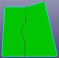
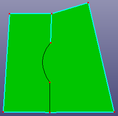
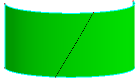
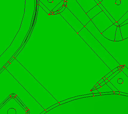
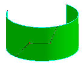
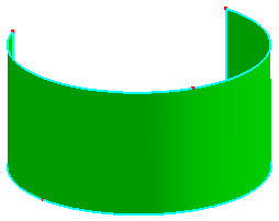
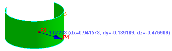
- Split Face
Choose two guided points on the face boundaries to split face.
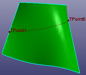
a. Select two positions on face boundary to split face (Split Face)
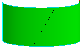
b. Results after trimming
- Cut Model
Select a cutting plane to cut whole model. The cutting plane can also be created by sketching. You can also reverse cutting direction by checking "Reverse Cut Direction".
a. Sketch a plane to cut model (Cut Model)
b. Results after cut model
- Multi Trim
Select multiple trim tools to trim an edge, a wire or a face.
a. Select 3 edges as trim tool to trim face (Multi Trim)
b. Results after trimming
You can translate, rotate, mirror or scale any shape or ref-geom by Transform tool.
To open Transform: Click Transform(Geometry Tools toolbar) or click Geometry, Geometry Tools, Transform.
Under Transform, select transform type:
- Translate
Select an axis as the translate direction. You can also create a temporary axis by click "." button to open the direction creation dialog.
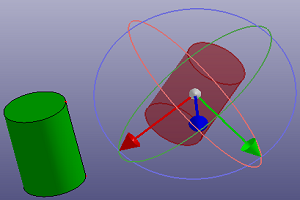
- Rotate
Select an axis as the rotation axis. You can also create a temporary axis by click "." button to open the direction creation dialog. If you want to modify the axis' position, you can select any point as the "Ref Pos." or click "." button to open the position creation dialog.
- Reflect
Select a point, axis or plane as the mirror reference object.
- Scale
Select a point as the scale reference object. If you want to scale shapes according to direction, select the direction in "Scale Dir.".
- Transform
Select two coordinate systems, and you can transform shapes from coordinate system 1 to coordinate system 2. You can also transform shapes freely by dragging on the visual coordinate system when "Free Edit" is checked.
- Affinity
Define a ref-coordinate system to do affinity transformation. You should define X, Y and Z scale factor.
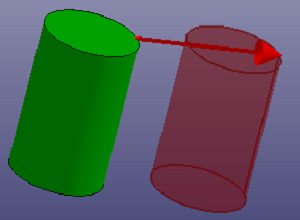
a. Translate
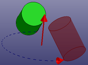
b. Rotate
c. Scale (Scale Dir. XYZ)
d. Scale (Scale Dir. X)
e. Scale (Scale Dir. Y)
f. Scale (Scale Dir. Z)
g. Reflect by point
h. Reflect by plane
i. Reflect by line
j. Transform by two coordinate systems
k. Transform freely
l. Before affinity transformation
m. After affinity transformation (scale factor X=1.0, Y=0.8 and Z=0.5)
Reverse edge, wire, face or solid's direction.
To open Reverse Direction: Click Reverse Direction (Geometry Tools toolbar) or click Geometry, Geometry Tools, Reverse Direction.
The edge, wire, face, shell or solid's direction can be reversed in this dialog.
Using Copy Entity tool to copy any shape or ref-geometry.
To open Copy Entity: Click Copy (Geometry Tools toolbar) or click Geometry, Geometry Tools, Copy .
Under Copy Entity, you can copy any shape or reference geometry. There provide four options:
- To Current Assembly
It will copy shapes to current assembly.
- To New Assembly
It will create a new assembly and copy shapes to this new assembly.
- To Specify Assembly
It will copy shapes to the specified assembly which is highlight in following list box.
- Move to Assembly
It will not copy shapes but directly move shapes from their raw assemblies to the specified assembly which is highlight in following list box.
- Move to Part
It will not copy elements but directly move elements form their raw parts to the specified part which is highlight in following list box.
In Geometry Management, you can blank/unblank or delete independent shapes and reference geometries, you can also export any shapes into IGES or step file, or clear all model. You can also convert new LSPP shapes to old LSPP data struct.
To open Management: Click Management(Geometry Tools toolbar) or click Geometry, Geometry Tools, Management.
Management supports:
- (un)Blank
Blank or unblank the selected independent shapes or reference geometry.
- Delete
Delete the selected independent shapes or reference geometry. As an exception, you can delete a face from a shell.
- (un)BlkAll
Blank or unblank the whole model.
- Export
Export selected shapes into IGES or step file.
- SplitShell
Split all shells and solids into independent faces.
- Glo/Loc
By default, the list box only lists the independent shapes' ID. Click Clo/Loc, it will lists all shapes' (dependent or independent) ID.
- To 2.X
Convert selected point, curve, surface into old lspp2.x data structure. You can view the converted results in the old UI by press F11 key.
- Undo
Undo the (un)blank or deleting operation.
- ClearModel
Remove all shapes or reference geometry from current model.
In Heal Model, you can fix all geometry errors, such as duplicated faces, small faces/edges, abundant vertices, holes. You can also modify any shape, such as replace edge from face, add vertex into edge, and so on.
To open Heal: Click Heal(Geometry Tools toolbar) or click Geometry, Geometry Tools, Heal.
Heal contains four basic parts:
Face. It contains several methods to fix or modify faces.
Edge. It contains several methods to fix or modify edges on face, edges on wire or independent edges.
Vertex. It contains several methods to fix or modify vertices on edge.
Hole. It contains two methods to remove holes from face or shell.
The Face contains:
- Duplicate
Search the duplicated or overlapped face pairs, and remove the small face.
- Small Face
Search the small faces according to size threshold, and remove the searched faces.
- Narrow Face
Search the long and narrow faces.
- Reshape
Rebuild the selected face by boundary smoothing and self-intersection fixing
The Edge contains:
- Toggle
If one face can't be stitched well with neighbor face in Stitch dialog because the gap is larger than the tolerance, you can select the free edge to sew two faces together by a larger tolerance. Toggle is a manual stitching method.
- Untoggle
If you want to make a shared edge from two faces into two free edges, you can use Untoggle to unstitch one shared edge.
a. raw shell
b. toggle the gap by select one edge
c. untoggle the top edge
- Replace
Replace the raw edge/wire with another edge/wire, the selected two edges/wires should locate at the same face.
a. Raw face and a projected wire on the face
b. Replace the face bound wire with the projected wire
a. Raw wire and an edge
b. Replace the bottom edge
a. raw two faces
b. replace the right face's bound edge with the left face's bound edge
- Small Edges
Search the small edges by length and angle tolerance, and finally remove them from face.
- Break
Break edge into pieces according to the angle threshold. You can also break edge by Break Curve.
a. Raw face
b. Break points on the faces' bound
- Duplicate
Search the duplicated or overlapped edges.
- Suppress
Tag the shared edge to suppressed edge or tag suppressed edge back to shared edge. In AutoMesh module, if the edge is suppressed, meshing will not pay loads in suppressed edge.
a. Raw shell with two faces
b. Tag the shared edge to suppressed edge
c. Auto Mesh without using suppressed edge
d. Auto Mesh using suppressed edge (Mesh across suppressed edges)
- Add
Insert a vertex into a edge, it means break the edge into two sub edges according to the selected point position.
a. Raw face
b. Add 3 vertices into the bound edges
- Move
Move a vertex on an edge to a specified position. The two vertexes shouldn't be too far away.

a. Raw face
b. New face after moving vertex
- Remove
Search the vertices on the face, shell or solid. These vertices are not necessary for the modeling procedure. Such as you can merge two neighbor edges into one edge, if the shared vertex on the two neighbor edges has the same tangent direction. The abundant vertices will be removed.
a. Raw shell
b. Shell after removing abundant vertices
- (un)Suppress
Tag shared vertices from edge to suppressed or tag suppressed vertices to shared. In AutoMesh module, suppressed vertices will not be paid load.
- Duplicate
Search duplicated vertices and ref-points.
The Hole contains:
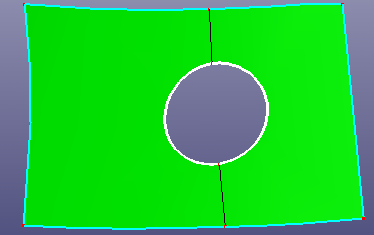
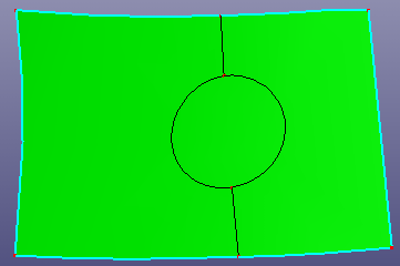
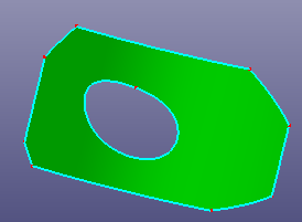
- Inner Hole
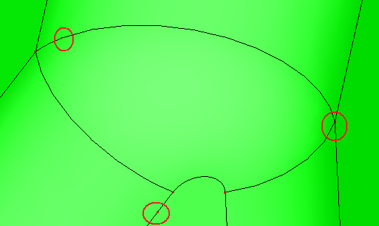
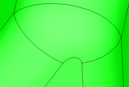
Inner hole is the inner boundary of the face. Search the inner hole and remove it from face.
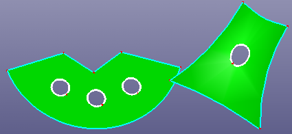
a. Raw faces
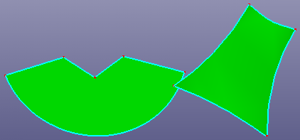
b. Faces after removing inner holes
- Out Hole
Out hole is the outer boundary of the shell. Search the out hole and fill the gap of the shell.
a. Out hole of the shell
b. Shell after filling out hole
Usually, the out hole is filled automatically. If the filling result is not satisfied, you can choose manual filling method.
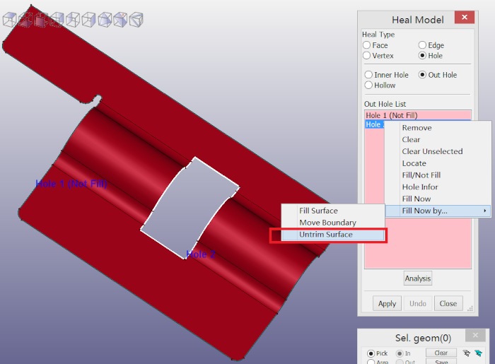
a. Untrim filling method
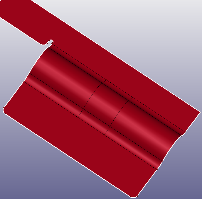
b. Result
- Hollow
Search hollow regions from shell or solid shape.
a. Solid contains many hollows

b. Searching and removing hollows
In Topology Simplify, you can untrim face, search and fix fillet surface, search and remove fillet edge, reshape face boundary, and remove inner loop face.
To open Topology Simplify: Click Topology Simplify (Geometry Tools toolbar) or click Geometry, Geometry Tools, Topology Simplify.
Topology Simplify contains six basic parts:
Untrim Surface
Unfillet Face
Unfillet Edge
Edge Reshape
Inner Region
Merge Same Surf
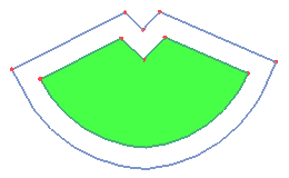
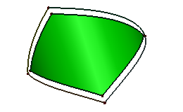
The Untrim Surface contains:
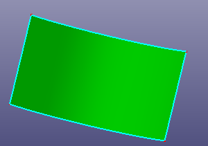
- All Trim Edges
Select face or wire from face to recover the raw surface bound. If the raw surface is period surface or B-spline surface, you can also check "Natural Bound" to recover its natural bound.
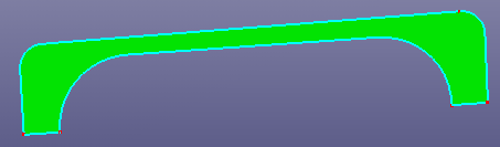
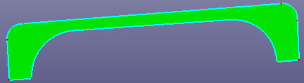
a. Raw trimmed face
b. Untrim the whole surface
a. Raw trimmed face and its basic surface is cylinder
b. Untrim the whole surface
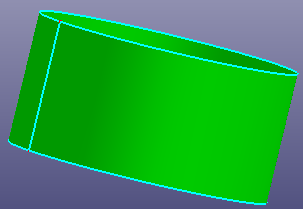
c. Untrim the whole surface and check "Natural Bound"
- Inner Trim Edges Only
Select wire from face or face, to remove all the inner edges (all holes)on the face.
- Manual Selection Edges
Select edges from face to simplify face boundaries. There provides three options: Connect End Points, Linear Extend Edges, and Natural Extend Edges. "Search" button is designed for quickly searching related free neighbor edges of one selected seed edge in the above list box.
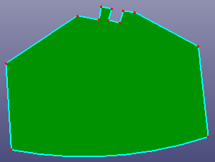
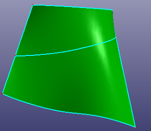
a. Raw face
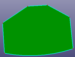
b. Untrim surface by selecting top several edges (Connect End Points)
c. Untrim surface by selecting top several edges (Linear Extend Edges)
d. Untrim surface by selecting top several edges (Natural Extend Edges)
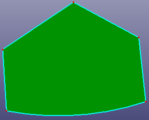
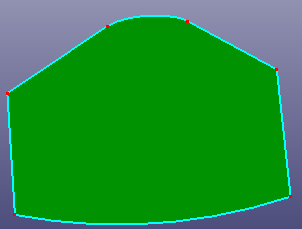
- Unfillet Face
The Unfillet Face try to search the fillet surface from the model, and try to remove the fillet surface by extending neighbor faces and trim with each.
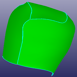
a. Raw faces
b. Faces after unfillet one surface
c. Faces after unfillet 4 surfaces
a. Raw faces
b. Faces after fillet surface removing
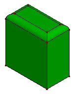
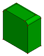
- Unfillet Edge
The Unfillet Edge try to search the fillet edges from the model, and try to remove the fillet edges by extending neighbor edges and trim with each.
a. Raw face
b. Face after fillet edge removing
- Edge Reshape
The Edge Reshape allow user select two positions on the face boundary, and try to regroup boundaries according to the edge tangent direction. The option "Join Reshaped Edges" will connect two new tangent curves into one curve. The option "Only Apply to Face" will only regroup the face boundaries and will not stitch this new face to other neighbor faces.
a. Select two positions on raw face
b. Face after reshape edge
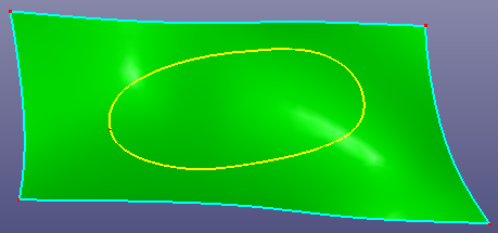
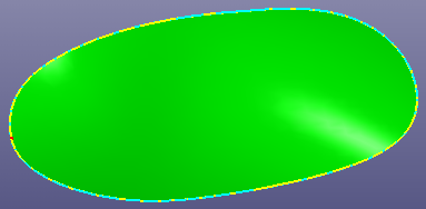
- Inner Region
The Inner Region allow user select seed face to remove all inner loop faces which locate inside the seed face and untrim the seed face at the loop region.
a. Select one seed face
b. remove inner face loop in seed face and untrim the loop region
- Merge Same Surf
The Merge Same Surf search two faces which has the same geometry surface from a shell, and finally merge them together.
a. Raw shell has two faces, they are from a cylinder surface
b. Search and merge
In Measure, you can measure the distance between two points, the radius and angle of the circular arc, the normal of the plane, whether two circle is co-center, whether two line is parallel, and so on. You can also show or hide the ID of any shape.
To open Measure: Click Measure(Geometry Tools toolbar) or click Geometry, Geometry Tools, Measure.
In Measure, you can show or hide faces, edges or vertices ID. If you select any shape, the geometry information of the shape will be listed. If two shapes selected, it will evaluate the relationship between the two selected shapes. If more that two shapes selected, it will only list the new selected shape geometry information.
To check any two points' distance, check Measure Points' Distance.
Measure two points' distance
To check gap between two neighbor edges, check Measure Edges' Gap.
Measure edges' gap
To measure two neighbor faces' normal angles in shared edge, check Measure Faces' Angle Diff.
a. Two faces share one edge
b. Shared edge sampled normals in two faces
To measure distance between edge and face, check Measure Edge to Face Distance.
Distance from edge to face
To visualize sampling points of curve, check Show Points on Curve.
Show points on edge
In Text Object, you can create text's curve, surface or solid shape. Currently, it's only available in Windows platform.
To open Text Object: Click Text Object (Geometry Tools toolbar) or click Geometry, Geometry Tools, Text Object.
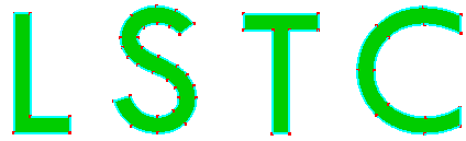
In Text Object, you can create text's curve, surface or solid shape. You can also change text object's font.
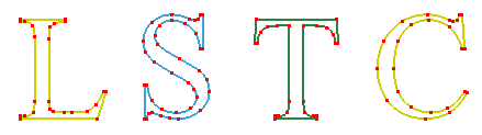
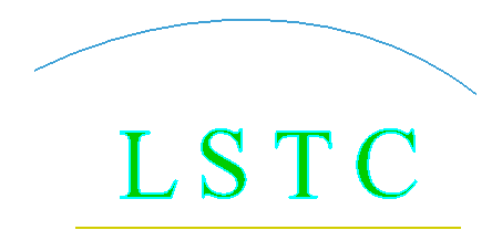
a. Curve of text "LSTC"
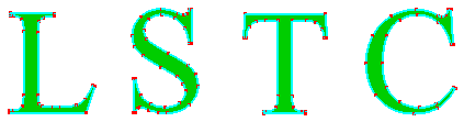
b. Surface of text
c. Surface of text using font "Tw Cen MT"
d. Solid of text
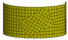
e. Result of text's solids using Solid Mesher
This is another geometry transform dialog. In this dialog, you can align shapes, array creating shapes, make shapes flow along curve, make shape shear and twist.
To open Array Flow: Click Array Flow (Geometry Tools toolbar) or click Geometry, Geometry Tools, Array Flow.
In the dialog, select the type you want to transform:
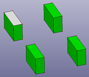
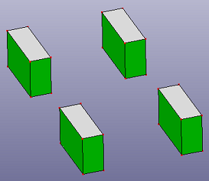
- Align
Select shapes to align in specified direction or position.
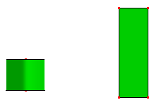
a. Raw shapes.
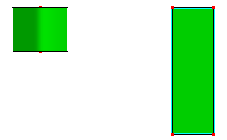
b. After align in top
- Array
Define array numbers and distance in X, Y and Z direction.
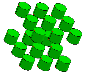
Array number in X, Y, Z are 3, 3 and 2
- Array on Curve
Array selected shapes on a curve. If the curve is laid on some surface, check "Curve on Surface" to make its transformation with surface normal.
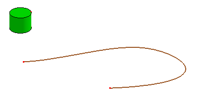
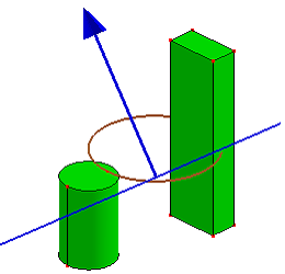
a. A curve and a cylinder
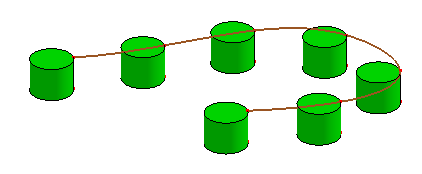
b. Array cylinder on the curve
- Array Polar/Surf
Array select shapes on a circle or surface.
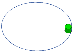
a. A circle and a cylinder
b. Array Polar
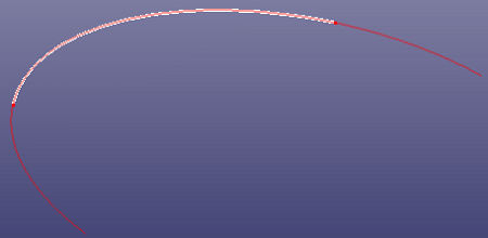
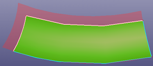
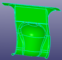
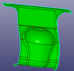
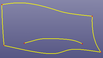
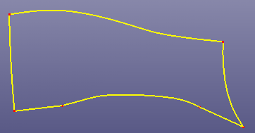
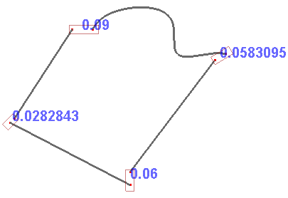
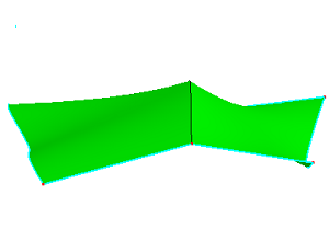
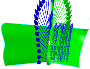
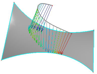
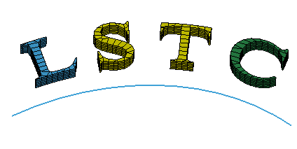
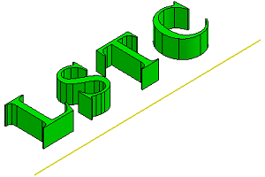
- Flow
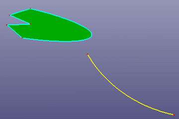
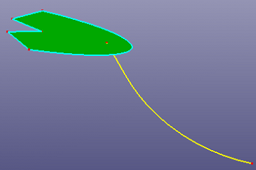
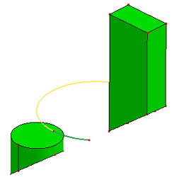
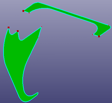
Re-aligns an object or group of objects from a base curve to a target curve. Select the base curve near one end, and select the target curve near the matching end. It will auto adjust curve's ends.
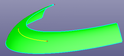
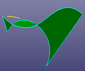
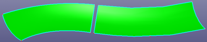
a. Yellow curve as base curve, blue curve as target curve.
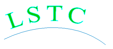
b. "LSTC" surface align with the blue curve

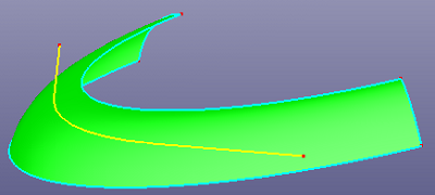
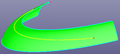
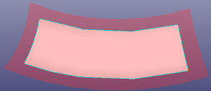
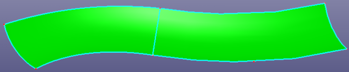
c. Check "Stretch".
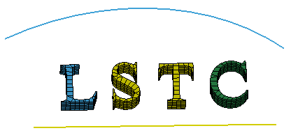
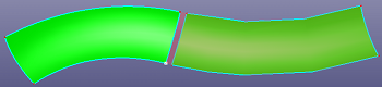
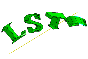
a. Yellow curve as base curve, blue curve as target curve. Check "Pick FEM"
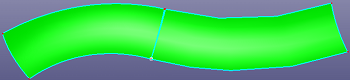
b. Check "Stretch", "LSTC" solid parts align with the blue curve
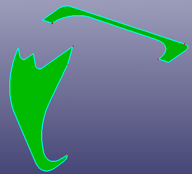
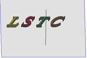
- Shear
Transform an object by shifting it at a specified angle parallel to the selected plane. Pick a plane as base plane, pick a line in the plane as the shear axis and define the angle to deform.
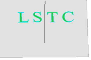
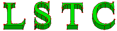
a. Raw "LSTC" faces
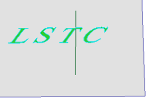
b. Shear result using angle 30 (The gray region is the base plane, the green vertical line is the shear axis.)
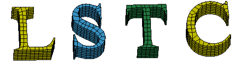
a. Raw "LSTC" solid parts
b. Shear result using angle 30
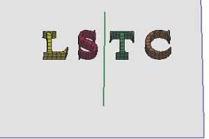
- Twist
Transform an object by shifting it at a specified angle parallel to the selected plane. Pick a plane as base plane, pick a line in the plane as the shear axis and define the angle to deform.
a. Raw "LSTC" solid shapes
b. Twist with angle 180
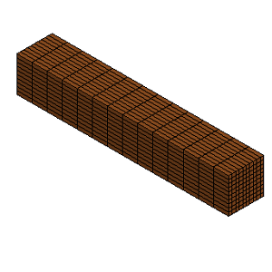
a. Raw solid parts
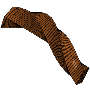
b. Twist using angle 240