- Identify
Display the ID for any node/element/part in the model.
- Find
Find a node/element/part by entering its unique ID.
- Blank
Blank selected nodes adn elements.
- Move/Copy
Move, copy, and organize elements.
- Offset
Offset shell mesh in direction of normals.
- Transform
Reflect,project,translate,transform,scale and rotate model entities with option to copy.
- Normal
Visualize and modify element normals.
- Detach Elem
Sever attachements between adjacent nodes and elements.
- Duplicate Node
Identify and remove duplicate nodes.
- Measure
Make measurements and create local coordinate systems.
- Morph
Morphing interface.
- Smooth
Mesh smoothing interface.
- Part Trim
Trim meshed parts with curves.
- Part Travel
Measure part to part distance and perform auto-positioning.
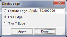
- Display Edge
Display edges.
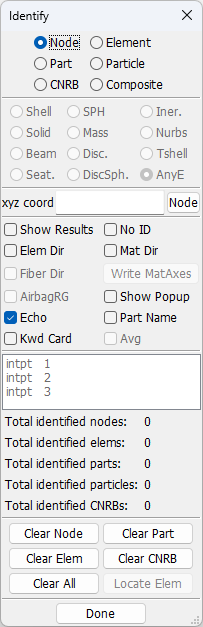
Use this interface to display the ID for any node, element, part, particle, constrained nodal rigid body (CNRB), or part_composite(_contact, tshell) in the model. The General Selection interface is used for entity selection.
- Shell
Select shell elements.
- Solid
Select solid elements.
- Beam
Select beam elements.
- Seat
Select seatbelt element.
- SPH
Select SPH elements.
- Mass
Select mass element.
- Disc.
Select discrete element.
- DiscSph.
Select discrete sphere element.
- Iner.
Select inertia element.
- Nurbs
Select Nurbs element.
- Tshel
Select Tshell elements.
- AnyE
Select any element.
- Key in xyz coord
Enter XYZ coordinates to be highlighted (separate each value with a comma or space).
- Show Results
Show Fringe Component results in Command Window.
- Elem Dir
Show element N1->N2 direction.
- Mat Dir
Show element material direction.
- Show Popup
Show info in popup window.
- Part Name
Show part name for selected parts.
- No ID
Do not show ID on picked elements.
- AirbagRG
Show airbag reference geometry.
- Echo
Turn on/off echo of identified items in message dialog.
- Clear Node
Clear all identified nodes.
- Clear Part
Clear all identified parts.
- Clear Elem
Clear all identified elements.
- Clear CNRB
Clear all identified CNRBs.
- Clear All
Clear all identified entities.
- Done
Exit Identify interface.
Use this interface to find a node/element/part by entering its unique ID.
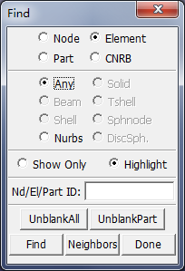
- Any
Find elements of any element type.
- Beam
Find beam elements.
- Shell
Find shell elements.
- Nurbs
Find Nurbs elements.
- Solid
Find solid elements.
- Tshell
Find Tshell elements.
- Sphnode
Find SPH elements.
- DiscSph
Find discrete sphere elements.
- Show Only
Show the entity only.
- Highlight
Highlight the entity.
- Nd/El/Part ID
Enter ID.
- UnblankAll
Unblank all blanked elements.
- UnblankPart
Unblank part of found elements.
- Find
Find and display the entity data.
- Neighbors
Find neighboring nodes/elements.
- Done
Exit Find interface.
This interface provides various methods of blanking (that is, hiding or masking) selected entities. Unlike SelPar, which allows entire parts to be turned on/off, Blank operates primarily at the element level. This interface is available for both pre and post-processing phases. Select entities using the General Selection interface.
- Shell
Select shell elements.
- Solid
Select solid elements.
- Beam
Select beam elements.
- Seat
Select seatbelt element.
- SPH
Select SPH elements.
- Mass
Select mass element.
- Disc.
Select discrete element.
- DiscSph.
Select discrete sphere element.
- Iner.
Select inertia element.
- Nurbs
Select Nurbs element.
- Tshel
Select Tshell elements.
- AnyE
Select any element.
- UnBlank Part
Unblank picked part.
- Auto-Apply
Automatically perform Apply after selection.
- Auto-Update
Automatically update solid outer surfaces and edges after blanking.
- Blank All
Blank all visible elements.
- Unblank All
Unblank all elements.
- Reverse
Reverse blanked/un-blanked elements.
- Update Surf
Update the 3D outer surface.
- UpdateEdge
Update edge line.
- Unblank Last
UnBlank last blanked elements.
- Done
Exit Blank interface.
Using this tool to Move or Copy selected elements from one part to another. For the copy option, the starting node and element IDs of the new elements can be automatically assigned by LS-PrePost or controlled by the user.
- Move
move selected elements to target part.
- Copy
copy selected elements to target part.
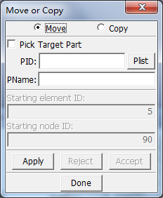
- Pick Target Part
Check this to pick a target part for move or copy elements.
- Plist
To select a target part from the popuped dialog.
- Apply
Apply operation to move or copy selected elements to target part.
- Accept
Accept the operation.
- Reject
Reject the operation.
This interface can be used to offset elements along average shell normals. The Copy Elements option will make a copy of the offset elements and retain the original elements in their initial state. Shell element normals for the selected elements are required to be consistent (shell normals can be checked and corrected using the Normals Interface).
This interface has variety of applications such as creating a punch part from a die in metal forming. Often shell parts are not meshed at their proper mid-surface. This can result in initial penetration conditions with adjacent parts. Offsetting shells provides a method of resolving such conflicts without having to remesh the part from scratch.
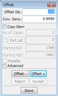
- Offset Dis.
Enter amount of offset
- Curv. Sens.
Curvature sensitive value (0.92 to 0.9999).
- Copy Elem
Copy elements while offsetting the model.
- No of Copies
Enter no of copies to be created.
- Part List
Popup part ID table for selection.
- Starting EID
Enter starting element ID.
- Starting NID
Enter starting node ID.
- Transfer
Transfer selection to newly copied elements.
- Advanced
Turn on the advanced shell offsetting.
- Offset -
Offset shell in negative normal direction.
- Offset +
Offset shell in positive normal direction.
- Reject
Reject the offset operation.
- Accept
Accept the offset operation.
- Done
Exit offset interface.
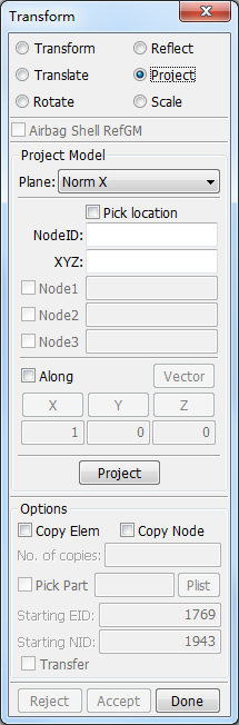
This interface supply tools for model management, include Transform, Translate, Rotate, Reflect, Project and Scale.
- Transform
Provides a means to transform parts or selected elements from one coordinate system to another.
- Translate
Translate selected nodes.
- Rotate
Rotate selected nodes.
- Reflect
Reflect or mirror selected nodes about a plane.
- Project
Projecting nodes to a plane,to a mesh,or to CAD curves.
- Scale
Scale selected nodes.
Purpose:
This interface provides various methods of projecting nodes to a plane, to a mesh, or to CAD curves. The planes can be normal to global x, y, z directions or normal to a vector defined by 2 nodes or a plane defined by 3 nodes.
Optionally the projection can be performed on a copy of the selected elements. In this case the original selected elements are retained at their starting location.
Function:
Project selected nodes to given target.
Sample:
No sample.
Dialog:
Common Controls:
Plane : Select plane of projection.
Copy Elem : Copy elements while transforming the model.
Copy Node : Copy nodes only while Transforming the model.
Part list : Popup part Id table for selection.
No. of copies : Enter no. of copies to be created.
Starting EID : Enter starting element ID.
Starting NID : Enter starting node ID.
Transfer : Transfer selection to newly copied elements.
Project : Perform projection for selected nodes.
Reject : Reject the operation.
Accept : Accept the operation.
Done : Exit interface.
Project Model by plane Norm X/Norm Y/Norm Z/N1-N2/N1-N2-N3 :
Pick location. : Pick a node on the plane of projection.
NodeID : Enter a node ID on the plane of projection (Hit enter to accept).
XYZ : Enter x, y, z coordinates on the plane of projection.
Node1 : Enter first node ID for N1-N2 and N1-N2-N3 planes.
Node2 : Enter second node ID.
Node3 : Enter third node ID.
Along : Project nodes along specified direction.
Vector : Define direction for projection.
X : Set direction 1,0,0.
Y : Set direction 0,1,0.
Z : Set direction 0,0,1.
Project Model by plane To Mesh:
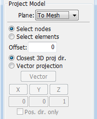
Select nodes : Select nodes to project.
Select elements : Select elements to project to.
Offset : Enter offset value of project nodes.
Closest 3D proj dir. : Project nodes to mesh in closest 3D direction.
Vector projection : Project nodes in specified vector direction.
Vector : Define direction for projection.
X : Set direction 1, 0, 0.
Y : Set direction 0, 1, 0.
Z : Set direction 1, 0, 0.
Pos. dir. only : Project only in positive vector direction.
Project Model by plane To Curve:
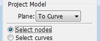
Select nodes : Select nodes to project.
Select curves : Select curves to project to.
Project Model by plane To Surface:
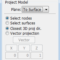
Select nodes : Select nodes to project.
Select surfaces : Select surfaces to project to.
Closest 3D proj dir. : Project nodes to surfaces in closest 3D direction.
Vector projection : Project nodes in specified vector direction.
Vector : Define direction for projection.
X : Set direction 1, 0, 0.
Y : Set direction 0, 1, 0.
Z : Set direction 1, 0, 0.
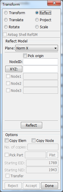
Purpose:
This interface is used to reflect or mirror selected nodes about a plane. The reflection plane can be specified in a number of ways:
1. Normal to global x, y, or z directions
2. Normal to a general vector defined by 2 nodes
3. A plane defined by 3 nodes
The position of a reflection place can be defined by picking a node or keying in the coordinatess of a point on the plane. Reflections can be performed on selected nodes or a copy of the nodes. The copy option will retain the selected nodes at their original location.
Purpose:
Reflect selected nodes with given plane.
Sample:
No sample.
Dialog:
Common Controls:
Plane : Select plane of reflection.
Pick Origin : Pick a node as the origin of the reflection.
NodeID : Enter a node ID as the origin of the reflection (Hit enter to accept).
XYZ : Enter x,y,z coordinates as the origin of the reflection.
Node1 : Enter first node ID to define plane.
Node2 : Enter second node ID to define plane.
Node3 : Enter third node ID to define plane.
Reflect : Perform reflection for the selected nodes.
Copy Elem : Copy elements while transforming the model.
Copy Node : Copy nodes only while Transforming the model.
Part list : Popup part Id table for selection.
No. of copies : Enter no. of copies to be created.
Starting EID : Enter starting element ID.
Starting NID : Enter starting node ID.
Transfer : Transfer selection to newly copied elements.
Reject : Reject the operation.
Accept : Accept the operation.
Done : Exit interface.
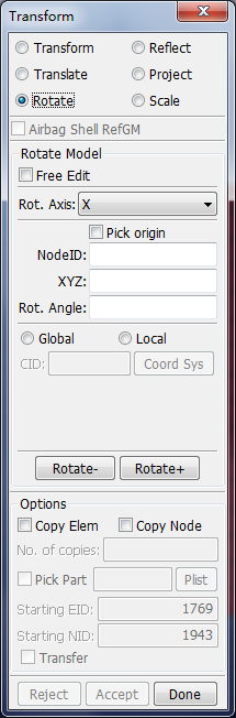
Purpose:
This interface is used to rotate selected nodes. The rotation direction and angle can be specified using various methods for maximum flexibility to suit different user needs. Optionally the rotations can be performed on multiple copies of the selected elements. The Tran option is only available when the Copy Element option is activated. This option automatically deselects the original nodes and selects the copied nodes (ready to perform the next operation with the copied set).
Function:
Rotate selected nodes with given direction.
Sample:
No sample.
Dialog:
Common Controls:
Rot. Axis : Select axis/plane of rotation.
Pick origin : Pick a node as the origin of rotation.
NodeID : Enter node ID as the origin of rotation (Hit enter to accept).
XYZ : Enter x, y, z coordinates as the origin of rotation.
Rot. Angle : Enter angle of rotation in degrees.
Copy Elem : Copy elements while transforming the model.
Copy Node : Copy nodes only while Transforming the model.
Part list : Popup part Id table for selection.
No. of copies : Enter no. of copies to be created.
Starting EID : Enter starting element ID.
Starting NID : Enter starting node ID.
Transfer : Transfer selection to newly copied elements.
Rotate - : Rotate the selected nodes in positive direction.
Rotate + : Rotate the selected nodes in negative direction.
Reject : Reject the operation.
Accept : Accept the operation.
Done : Exit interface.
Rotate Model with Axis x, y or z:
Global : Translation will be in global direction.
Local : Translation will be in local system.
Coord sys : Click button to select Coordinate system.
CID : Enter coordinate system ID, 0 = global.
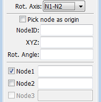
Rotate Model with Axis defined by user selected nodes:
Node1 : Pick Node1 to define N1-N2 axis..
Node2 : Pick Node2 to define N1-N2 axis..
Node3 : Pick Node3 to define axis normal to N1-N2-N3.
Purpose:
This interface is used to scale selected nodes. The scaling direction and factor can be specified using various methods for maximum flexibility to suit different user needs. Optionally the scaling can be performed on multiple copies of the selected elements. The Tran option is only available when the Copy Element option is activated. This option automatically deselects the original nodes and selects the copied nodes (ready to perform the next operation with the copied set).
Function:
Scale selected nodes with given direction and scale factor.
Sample:
No sample.
Dialog:
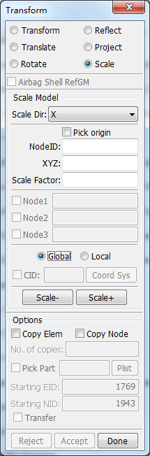
Scale Dir : Select direction of scaling.
Pick node as origin : Pick a node as the origin of scaling .
NodeID : Enter a node ID as the origin of the scaling (Hit enter to accept).
XYZ : Enter x,y,z coordinates as the origin of the scaling.
Scale Factor : Enter scale factor.
Node1 : Enter first node ID for N1-N2 and N1-N2-N3 planes.
Node2 : Enter second node ID for N1-N2 and N1-N2-N3 planes.
Node3 : Enter third node ID for N1-N2 and N1-N2-N3 planes.
Global : Scale will be in global system.
Local : Scale will be in local system.
CID : Pick local scale coordinate system.
Coord Sys : Click button to select coordinate system.
Copy Elem : Copy elements while transforming the model.
Copy Node : Copy nodes only while Transforming the model.
Part list : Popup part Id table for selection.
No. of copies : Enter no. of copies to be created.
Starting EID : Enter starting element ID.
Starting NID : Enter starting node ID.
Transfer : Transfer selection to newly copied elements.
Scale- : Scale the model down with selected nodes.
Scale+ : Scale the model up with selected nodes.
Reject : Reject the operation.
Accept : Accept the operation.
Done : Exit interface.
Purpose:
This interface provides a means to transform parts or selected elements from one coordinate system to another. Transformation is generally useful for positioning operations that require a combination of translation and rotation. The definition of a coordinate system requires 3 sets of coordinates. These can be input by selecting 3 nodes, keying in coordinates, or picking positions using the 'Create Position' sub-interface. The first set of 3 points defines a coordinate system for 'From' (the source position), and the second set of 3 points defines a coordinate system for 'To' (the target position).
By activating the Copy Elem option, the transformation is applied to a copy of the elements as opposed to the selected nodes. The selection of nodes to transform can be made various ways using the General Selection Interface, but in the end it is only the nodes that get transformed.
Function:
Transform Nodes : Transform selected nodes from one coordinate system to another coordinate system.
Copy Element : Copy element as opposed to the selected nodes to target part.
Sample:
Sample1: Show how to copy element while transforming the model.
Dialog:
From : Form the coordinate system the model will transform from.
P1 : Get position for from point 1.
P2 : Get position for from point 2.
P3 : Get position for from point 3.
To : Form the coordinate system the model will transform to.
P1 : Get position for to point 1.
P2 : Get position for to point 2.
P3 : Get position for to point 3.
Reset : Reset transform coordinate system.
Transform : Apply transformation.
Copy Elem : Copy elements while transforming the model.
Copy Node : Copy nodes only while Transforming the model.
Part list : Popup part Id table for selection.
No. of copies : Enter no. of copies to be created.
Starting EID : Enter starting element ID.
Starting NID : Enter starting node ID.
Transfer : Transfer selection to newly copied elements.
Reject : Reject the operation.
Accept : Accept the operation.
Done : Exit interface.
Purpose:
Show how to copy element while transforming the model.
Step 1:
Run lspp and load any .k model file, open Transform dialog, select Transform method.
Step 2:
Check 'From' and pick nodes in the graphic view to get from coordinate system.
Check 'To' and pick nodes in the graphic view to get to coordinate system.
Step 3:
Check 'Copy Elem' option.
Pick nodes in the graphic view for transform, note that the picked nodes should in the same elements.
Step 4:
Click 'Transform' and 'Accept' to finish the operation.
Purpose:
This interface is used to translate selected nodes. The translation direction and distance can be specified using various methods for maximum flexibility to suit different user needs. Optionally the translations can be performed on multiple copies of the selected elements or nodes. The Tran option is only available when the Copy Element option is activated. This option automatically deselects the original nodes and selects the copied nodes (ready to perform the next operation with the copied set).
Function:
Translate selected nodes in given direction.
Sample:
No sample.
Dialog:
Common Controls:
Direction : Select direction of translation.
Distance : Enter distance of translation.
Global : Translation will be in global direction.
Local : Translation will be in local system.
Coord sys : Click button to select Coordinate system.
CID : Enter coordinate system ID, 0 = global.
Copy Elem : Copy elements while transforming the model.
Copy Node : Copy nodes only while Transforming the model.
Part list : Popup part Id table for selection.
No. of copies : Enter no. of copies to be created.
Starting EID : Enter starting element ID.
Starting NID : Enter starting node ID.
Transfer : Transfer selection to newly copied elements.
Tran - : Translate in negative direction.
Tran + : Translate in positive direction.
Reject : Reject the operation.
Accept : Accept the operation.
Done : Exit interface.
Translate Model in Direction x, y or z:
Translate distance : Enter distance of translation.
Translate Model in Direction xyz:
Enter X, Y, Z distance : Enter distance of translation.
Translate Model in Direction defined by selected nodes:
Translate distance : Enter distance of translation.
Node1 : Pick Node1 to define N1-N2 direction.
Node2 : Pick Node2 to define N1-N2 direction.
Node3 : Pick Node3 to define Plane normal to N1-N2-N3.
Translate Model in Direction defined by two points:
P1 : Enter x,y,z coordinates to define pt1.
P2 : Enter x,y,z coordinates to define pt2.
Translate Model in Direction defined as the normal of selected shell element:
Translate distance : Enter distance of translation.
PickElm : Pick Element to choose normal.
EID : Enter element ID for normal.
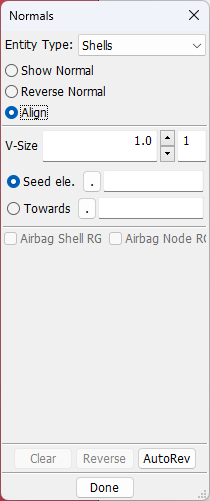
This interface is for reviewing and reversing shell, segment, solid, cohesive, beam, and thick shell normals. Consistent normals in a part may be required to meet mesh quality standards, for contact definitions in LS_DYNA, and also for post-processing shell results at various integration points. Uniformly aligned normals are also required before performing a shell offset operation.
- Shell
Pick shell elements to operate.
- Segment
Pick segments to operate.
- Tshell
Pick tshell elements to operate.
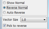
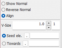
- Show Normal
Use general selection to show element normal.
- Reverse Normal
Interface to reverse element normal.
- Align
Align normals to be topologically consistent by using seed elements and pointing towards a coordinate.
- Vector Size
Set normal vector size (>1.0 larger).
- Compliment
Show back face color as compliment of part color.
- Dimmed
Show back face color as dimmed part color.
- Clear
Clear Shown normals.
- Reverse
Reverse all shown normals.
- AutoRev
Autoreverse normal according to seed element.
- Done
Exit this interface.
This dialog can be used to detach (disjoint) elements as well as break connectivity at individual nodes. Using the General Selection Interface elements can be picked for detachment with great flexibility.
- Shell
Detach shell elements by element or edge.
- Beam
Detach beam elements by element.
- Solid
Detach solid elements by element.
- Tshell
Detach tshell elements by element.
- Node
Detach nodes by node.
- Sample
A sample to show how to use it.
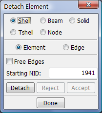
- Element
Select group of elements to be detached.
- Edge
Select edges of elements to be detached.
- Starting NID
Enter starting node ID.
- Free edges
Find and Show free edges.
- Detach
Detach the selected data.
- Reject
Reject the detach operation.
- Accept
Accept the detach operation.
- Done
Exit detach interface.
Disjointed meshes are often due to mesh generation of sub-domains of a single part which result in free nodes along internal edges. The Show Free Edges toggle displays free edges on the mesh. Such disjointed situations can be detected by finding pairs of nodes that are within a certain tolerance distance of each other. These nodes can then be combined using the Merge Duplicate Nodes button. Upon merging nodes within the user specified tolerance, an option to retain the largest or smallest node ID is available. By default the smaller node ID is retained.
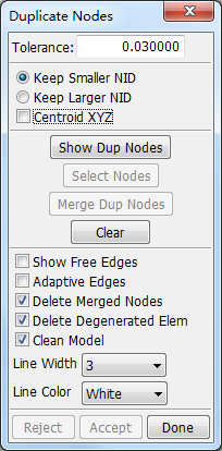
- Tolerance
Enter tolerance for finding duplicate nodes.
- Keep smaller NID
Keep nodes with smaller node ID.
- Keep larger NID
Keep nodes with larger node ID.
- Centroid XYZ
Move xyz to the centroid of the merged nodes.
- Show Dup Nodes
Find and show duplicated nodes.
- Select Nodes
Select partial duplicated nodes to merge.
- Merge Dup Nodes
Merge shown duplicated nodes.
- Clear
Clear all shown duplicated nodes.
- Show Free Edges
Find and show free edges.
- Adaptive Edges
On will treat adaptive edges NOT a free edge.
- Delete Merged Nodes
Delete unreferenced nodes.
- Delete Degenerated Elem
Delete degenerated elements.
- Clean Model
Clean invalid data in whole model.
- Line Width
Select free edge line width.
- Line Color
Select free edge line color.
- Reject
Reject the duplicate node operation.
- Accept
Accept the duplicate node operation.
- Done
Exit detach interface.
This interface is used to make measurements of various aspects of the model and to create local coordinate systems. It is available for pre and post-processing phases. If an LS_DYNA keyword file or project file is loaded, measurements are limited to single values. If post-processing files are loaded, measured quantities wil be XY plotted. Measurements can be done in the global coordinate system (default) or optionally in a local coordinate system. Upon selecting a local coordinate system, the displacements and coordinates can be measures with respect to that coordinate system.
- Basic.
Basic functions to measure variables of model.
- Affixation
Added functions, such as create local coordinate system, separation and so on.
Sample
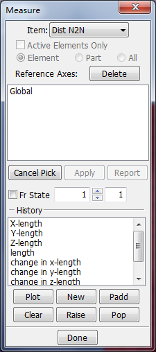
- Item
Select an item to measure/Create local coordinate system. ( Coordinate, Dist N2N, Dist N2S, Dist P2P, Angle 3Node, Angle 4Node, 3Pt Radius, Area, Volume, Mass, Inertia, Ang Vel, Create Axes, Separation).
- Active Elements Only
Measure part(s) using active elements. ( some elements can be blanked. See blank interface in details).
- Element
Display measurement for selected elements.
- Part
Display measurement for selected parts.
- All
Display measurement for all visible parts.
- Reference Axes list
Select current reference axes for measurement.
- Delete
Delete selected axes.
- Cancel Pick
Cancel the last picked node.
- Apply
Apply for displayed parts.
- History list
Select history type to plot.
- Plot
Plot history data in current XY-Plot window.
- New
Plot history data in a new XY-Plot window.
- Padd
Add history data to current XY-Plot window.
- Clear
Clear selected items in list.
- Raise
Raise all open XY-Plot windows.
- Pop
Open and raise all closed XY-Plot windows.
- Done
Exit the measure interface.
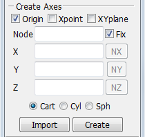
Create local coordinate system:
- Origin
Pick point for axes origin.
- Xpoint
Pick point for direction of X axes.
- XYplane
Pick point to define XY plane of axes.
- Node
Pick or selected node number.
- Fix
Pick or selected node number.
- X,Y,Z
Enter or show global x, y or z component value.
- NX,NY,NZ
Set components into x, y or z direction.
- Cart
Set local system to Cartesian.
- Cyl
Set local system to Cylinderical.
- Sph
Set local system to Spherical.
- Import
Read local system from a file.
- Create
Local system creation dialog.
Separation:
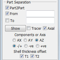
- Part2Part
Select part to part separation or part to a reference state.
- From
Enter part id for fringe.
- To
Enter part id or reference state.
- Show
Compute separation fringes.
- Tracer
Show or clear separation distance nodal tracers.
- Axial
Separation along axial direction X,Y or Z.
- Components or Axis AX, AY, AZ
Select X, Y, Z axial separation distance.
- -/+
Distance between parts in +ve and -ve directions.
- -ve
Distance in -ve direction only.
- +ve
Distance in +ve direction only.
- Shell thickness offset T1, T2
Allow for shell thickness in part1 and part2.
This interface is for morphing of an existing mesh.
- Solid Cons
This method works by constraining the parts to be morphed (Morph nodes) within a solid hex mesh (Con. Ele.). Once Constrain has been activated, the hex mesh can be transformed in any way, and the Morph nodes will follow. The nodal coordinates are transformed based on their relative position within their containing solid element. Thus in order to make more precise adjustments, a finer solid mesh should be used.
- 8 Lines Cons
This method works by mapping the parts to be morphed between a set of 8 line (4 Source and 4 Target). It is similar to the first method except the solid mesh generation is done transparently and automatically.
- Mesh Cage
This tool lets user select a part of element (shell/solid) and a cage containing the selected elements will be displayed. User can select and move the control points of the cage to modify the shape of the cage, and the shape of the contained elements are modified in time too.
- Mesh Box/ Interior
This tool helps user select a part of shell element and select a node to morph.
- Mesh Unfolding
This tool helps user unfold 3D mesh data into 2D mesh data.
- BPM_NODE gen.
Under Construction...
Sample
- Mesh morphing by mesh cage
A tutorial to how to morph a mesh by mesh cage.
- Mesh morphing by mesh interior node
A tutorial to how to morph a mesh by mesh box/interior node.
- Mesh unfolding
A tutorial to how to unfold a 3D mesh to be a 2D mesh.
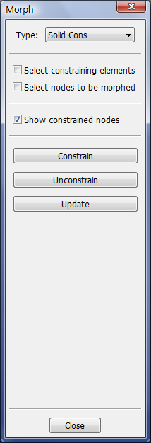
- Select constraining elements
Select solid elements acting as constraining boxes.
- Select nodes to be morphed
Select nodes to be constrained in elements.
- Show constrained nodes
Display constrained nodes.
- Constrain
Constrain nodes inside selected elements.
- Unconstrain
Unconstrain all nodes.
- Update
Force an update for the position of constrained nodes.
- Close
Exit Morph Interface.
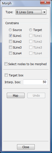
- Source
Select source lines.
- SLine1
Pick starting end of source line 1.
- SLine2
Pick starting end of source line 2.
- SLine3
Pick starting end of source line 3.
- SLine4
Pick starting end of source line 4.
- Target
Select target lines.
- TLine1
Pick starting end of target line 1.
- TLine2
Pick starting end of target line 2.
- TLine3
Pick starting end of target line 3.
- TLine4
Pick starting end of target line 4.
- Select nodes to be morphed
Select nodes to morph from source to target location.
- Target box
Retain the target boxes as solid elements.
- Interp. box
Number of boxes to reinterpolate the curves with.
- Map
Map nodes from source to target location.
- Undo
Undo map 8 lines operation.
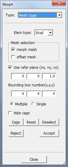
- Type:Mesh cage
Morphing element (shell/solid) by using option 'Mesh cage'.
- Elem type
Option of element type. Select 'shell' to morph shell element, select 'solid' to morph solid element.
- Mesh selection
When shell element was selected, Both 'morph mesh' and its 'offset mesh' are enabled, user can select a mesh and its offset mesh to morph together. When solid element was selected, only 'morph mesh' is enabled..
- Use refer plane (nx, ny, nz)
This vector (nx, ny, nz) is the normal of the plane which is used as a referenced plane for cage creation.
- Bounding box number (x,y,z)
The number of control point in three directions (x, y and z) for cage creation.
- 'Multiple' and 'Single' radio
The mode to select cage control point for moving. When 'Multiple' was selected, use can select multiple cage control points to move. When 'Single' was selected, user can only select a single cage control point to move.
- Hide cage
When this check box is selected, the cage control points disappear. When this check box is unchecked, the cage control points appear.
- 'Cage' button
Click this button to create cage control points.
- 'Reset' button
Click this button to reset all the mesh data as initial status.
- 'Deselect' button
When this button was clicked, all the selected cage control points are released as unselected status. This button helps user release the selected cage control points when user wants to select new control point.
- 'Reject' button
Reject the morphed mesh data.
- 'Accept' button
Accept the morphed mesh data and add them into database.
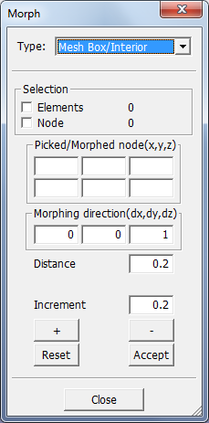
- Type:Mesh Box/Interior
Morph mesh by selecting elements and an interior node.
- Selection 'Elements'
When this check box is checked, user can select shell element. When elements were selected, a bounding mesh box will be figured out, but this mesh box will not be displayed, it is only used to define the morphing domain.
- Selection 'Node'
When this check box is checked, user can select a node to morph.
- Picked/Morphed node(x, y,z)
display the 3D coordinate values (x, y, z) of the picked node and morphed position.
- Morphing direction(dx, dy, dz)
the direction (dx, dy, dz) which the selected node morphs along.
- Distance
Morphing distance value from original position to morphed position.
- Increment
increment value for every morphing time.
- Button '+'
Morphing along the morphing direction.
- Button '-'
Morphing along the reverse direction.
- Button 'Reset'
Reject the morphed mesh data.
- Button 'Accept'
Accept the morphed mesh data and add them into database.
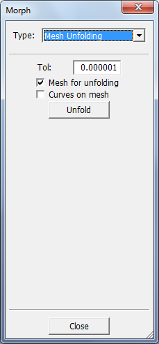
- Type:Mesh unfolding
Unfold a 3D mesh part into a 2D mesh part.
- Tol
Tolerance value checking tiny element. If the area of the element is smaller than this tolerance value, the element area will treated as zero.
- Mesh for unfolding
Select 3D mesh for unfolding.
- Curves on mesh
Select curves which are located on the mesh for unfolding, the 3D curves will be unfolded into 2D curves which still are located on the unfolded 2D mesh.
- Button 'Unfold'
execute Unfolding program.
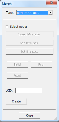
- Select BPM nodes
Select nodes that will get *BOUNDARY_PRESCRIBED_MOTION_NODE.
- Save BPM nodes
Save selected nodes for BPM generation.
- Set initial pos
Save coordinates for initial position.
- Set final pos
Save coordinates for final position.
- Initial
Show nodes in initial position.
- Final
show nodes for finial position.
- Reset
Reset node coordinates.
- LCID
Curve ID for BPM reference.
- Create
Create *BOUNDARY_PRESCRIBED_MOTION_NODE.
- Close
Exit Morph interface.
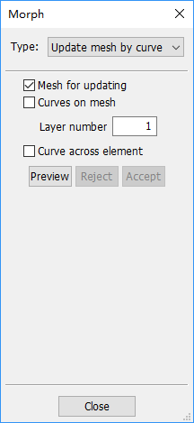
- Type
Modify local mesh around a curve which is located on the mesh by selecting the curve and defining the extending number.
- Curves on mesh
Select a curve which is located on a mesh.
- Layer number
How many layers the new element will generate. The layer number value which is used to define modification domain extending from the selected curve.
- Curve across element
Type of calculating the layer number. If this button is checked, the new element will across the curve. otherwise the new element will use the curve as boundary.
This interface is used to smooth existing 2D and 3D meshes.
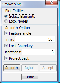
- Select Elements
Select elements to smooth.
- Lock Nodes
Select nodes to remain fixed during smoothing.
- Feature angle
Set angle above which to preserve mesh feature lines.
- Lock Boundary
Check to fix nodes along boundary of selected shell elements and nodes on the exterior faces of selected solid elements.
- Iterations
Enter number of smoothing iterations before projecting nodes back to original mesh surface.
- Project back
Project nodes back to geometry.
- Smooth
Smooth nodes for selected elements.
- Reject
Reject smoothing operation.
- Accept
Accept smoothing operation.
- Done
Exit Smooth Interface.
This interface can be used to trim (cut) parts with curves. The target application for this function is to trim parts after a metal stamping operation but it can be useful for other purposes as well. Note that if stresses, strains, and thicknesses are available (typically from dynain files), then upon trimming this data is updated. Adaptive constraints are also handled in the trimming process.
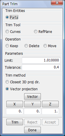
- Parts
when active, parts to trim can be selected by clicking on them in the graphics window.
- Curves
when active, curves that should be used for the trim/cut operation can be selected by clicking on them in the graphics window.
- RefPlane
when active, pick reference plane on graphic area used for the trim operation.
- Keep
If the Keep radio button is active, no elements will be deleted or moved to another part.
- Delete
when active, one seed element should be picked. the elements that are topologically connected to the seed elements will be deleted after the trimming operation is performed.
- Move
when active, one seed element should be picked. the elements that are topologically connected to the seed elements will be moved to a new part after the trimming operation is acceptedt.
- Limit
Elements further away than this distance will not be trimmed.
- Tolerance
Nodes close to the trim curve will be moved to the cutting surface if they are closer than Tolerance*element_size. This prevents very small elements from being created on the cut line.
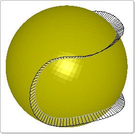
- Closest 3D proj dir.
The cutting surfaces are created from the curve definition and are extended in the normal direction of the closest element. This gives a cut on the selected parts as close as possible to the curve. This method is useful when the elements to be cut would be parallel or nearly parallel to the trim vector direction with the previous method. This method can, for example, trim the rubber cut line on a tennis ball, as shown in Figure 1, where the vector projection method would fail.
- Vector projection
The part(s) will be cut with cutting surfaces that are made from the curve and extruded the distance Limit in both positive and negative Vector direction.
- Vector
The general vector creation function can be activated.
- X/Y/Z
The vector direction is defined by the x, y, and z fields. X, Y, and Z buttons for quickly setting the vector to any of the global directions are also provided.
- Trim
The trim operation is executed.
- Reject
The trim operation can be rejected.
- Accept
The result will be displayed, and the trimmed elements can be kept.
- Done
Accepts the trim operation and exits the PTrim Interface.
This interface can be used to position the components involved in a forming siumlation (part, die, punch, blank, blank-holder, etc...) so that they are in exact contact at the beginning of the analysis.
Move a part reference to another part.
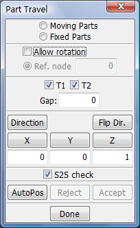
- Moving Parts
Select moving parts. The nodes of the Moving parts will be moved. Multiple parts can be selected.
- Fixed Parts
Select fixed parts. the Fixed parts acts like a contact surface. Multiple parts can be selected.
- Allow rotation
Select fixed parts. the Fixed parts acts like a contact surface. Multiple parts can be selected.
- Ref. node
The rotation point, which is the same as the reference point, can optionally be changed to be at any nodal position by activating the Ref. node toggle and picking a node with the left mouse button or typing a node ID in the text field. The stresses and strains on the *INITIAL_STRESS_SHELL, *INITIAL_STRAIN_SHELL, and *INITIAL_STRESS_SOLID keywords are automatically rotated to follow the rotation of the elements in the moving parts.
- T1
The thicknesses of the moving parts will be considered if the T1 toggle is active.
- T2
The thicknesses of the fixed parts will be considered if the T2 toggle is active.
- Gap
With either of these toggles active, an appropriate gap will be left between the moving and the fixed parts. The purpose for this is to make the parts "exactly in contact" as far as LS_DYNA is concerned. Additional clearance between the moving and the fixed parts can be added by typing a value in the Gap field.
- Direction
Popup direction dialog to define a vector.
- Flip Dir.
The direction of travel can be reversed.
- S2S check
Perform surface to surface check between parts.