


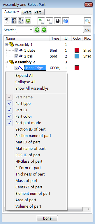
- Assembly and Selpart
Select which parts and assembly to display, delete.
- Keyword Manager
providing access to keyword editing and search interface.
- Create Entity
Generate entities, and use the drawing area to visualize entities while working on them
- Display Entity
Display LS_DYNA entities such as sets, contacts, rigidwalls, boundary, etcetera .
- RefCheck
Identify unreferenced, undefined, or attached entities.
- Renumber
Renumber IDs of model entities.
- Section Plane
Create cross sections of the model.
- Subsystem
Interact with an manage sub-systems.
- Group
Create and manipulate groups of parts
- View
Save and retrieve appearance, color, and orientation settings.
- Part Color
Apply different colors and transparency levels to selected parts.
- Appear
Change the appearance of selected parts.
- Model Selection
Open and select multiple models.
- Annotation
Add annotations to a model.
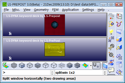
- Split Window
Split graphics region into multi-view.
- Explode
Explode/separate parts so that they can be viewed more easily.
- Light
Apply effects using up to ten independent light sources.
- PartD
operate part data.
This interface is used for general managment of parts, include FE parts, Geometry parts and part display set.
- Assembly
Integrated manage tool for FE parts and Geometry parts.
- GPart
Manage tool for Geometry parts.
- Part
Select parts to display.
There are total 18 columns on the tree list, such as "Name", "Type", "Id", "Color", etc. Right-click the header or blank area of the tree list can pop a menu to set display or not of each column.
- Displayed
Just show displayed parts on the tree.
-

Show all.

Blank all.

Reverse the display state of all FE parts and Geometry part.

Restore.

List Active Only.

List Inactive Only.

List Finite Element Only.

List Geometry Only.

Search FE parts or Geometry parts.
- Search
Input the object for search.

Search down.

Search up.

Set search conditions.
Menu items
- Expand All
Expand all assembly tree items.
- Collapse All
Collapse all assembly tree items.
- Show All Assemblys
Show all assembly tree items, some assembly tree item may be hidden if it has no children.
- Others
Set tree column shown/hiden.
Menu tool for assembly management
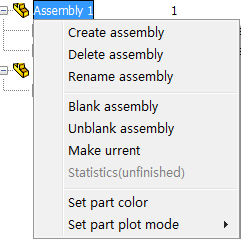
- Create Assembly
Create new assembly and make it as the current.
- Delete Assembly
Delete selected assembly.
- Rename Assembly
Rename selected assembly.
- Blank Assembly
Blank selected assembly, blank all parts that belong to this assembly.
- Unblank Assembly
Unblank selected assembly, unblank all parts that belong to this assembly.
- Make Current
Make selected assembly as the current, new created parts will set as children of this assembly automaticly.
- Statistics
Get statistic information for selected assembly.
- Set Part Color
Set the same color for all parts that belong to selected assembly with Set Color Dialog.
- Set Part Plot Mode
Set the same plot mode for all parts that belong to selected assembly.
Menu tool for FE part management
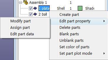
- Create part
Create new part.
- Edit part property
Edit part property with Part Property Dialog, include "Modify part", "Assign part" and "Edit part data".
- Delete parts
Delete selected parts.
- Blank parts
Blank selected parts.
- Unblank parts
Unblank selected parts.
- Set color of parts
Set the same color for all selected parts with Set Color Dialog.
- Set part plot mode
Set the same plot mode for all selected parts.
Menu tool for Geometry part management
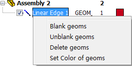
- Blank Geoms
Blank selected geometry parts.
- Unblank Geoms
Unblank selected geometry parts.
- Delete Geoms
Delete selected geometry parts.
- Set Color of Geoms
Set the same color for selected parts with Set Color Dialog.
Menu tool for Geometry part group management
- Create new
Create new geometry part group.
- Set current
Set selected geometry part group as the current.
- (Un)Blank
Blank or unblank selected geometry part group.
- Delete
Delete selected geometry part group.
- Color
Set color of selected geometry part group with Set Set Color Dialog.
- Locate
Locate selected geometry part group.
- Statistical
Get statistical information of selected geometry part group.
- To 2.x
Convert selected geometry part group items to version 2.4.
Menu tool for Geometry item management
- (Un)Blank
Blank or Unblank selected geometry items.
- Delete
Delete selected geometry items.
- Set GPart
Set geometry part group of selected geometry items.
- Color
Set color of selected geometry items with Set Color Dialog.
- Locate
Locate selected geometry items.
- Statistical
Get statistical information of selected geometry items.
- To 2.x
Convert selected geometry items to version 2.4.
- Model selection drop-down menu
For use when multiple models are loaded (Md1/Md2/Md3/etc...).
- Beam
Select/deselect Beam elements.
- Shell
Select/deselect Shell elements.
- Solid
Select/deselect Solid elements.
- Tshell
Select/deselect Tshell elements.
- Mass
Select/deselect Mass elements.
- Discrete
Select/deselect Discrete elements.
- Seatbelt
Select/deselect Seatbelt elements.
- Inertia
Select/deselect Inertia elements.
- Rsurf
Select/deselect Rigid-surface elements.
- SPHnd
Select/deselect SPH nodes elements.
- Fluid
Select/deselect Fluid elements.
- NumOrder
Display part list as numerical order, default is user order.
- Selected
List displayed parts only.
- Info
Show PART Info for selected parts.
- SortBy
Sort parts by prop/elform.
- All
Select all parts.
- None
Deselect all parts.
- Rev
Reverse part selection.
- Auto
Update selection automatically (Red=on).
- Apply
Update selected parts (when Auto=off).
- Restore
Restore the last removed part.
These subdialogs are accessed though several different command interfaces.
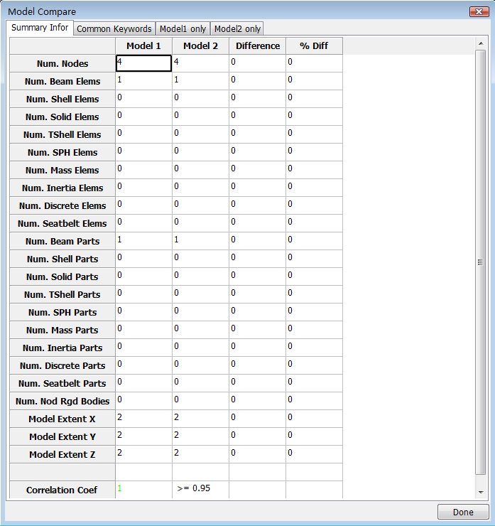
Compare all keywords of selected two models.
Operation Step:
Read in two different models, use ModelCompare_M1.k and ModelCompare_M2.k.
FEM->Model and Part->Model Selection.
Select radio button "Compare", select the two models in the model list.
Click button "Compare".
- 1. Summary Information
Gives the summary information of the selected two models, such as node count, element count, part count and etc.
- 2. Common Keywords
List all keywords exist in both model 1 and model 2. If someone is different in these two models, it will be highlighted with red color.
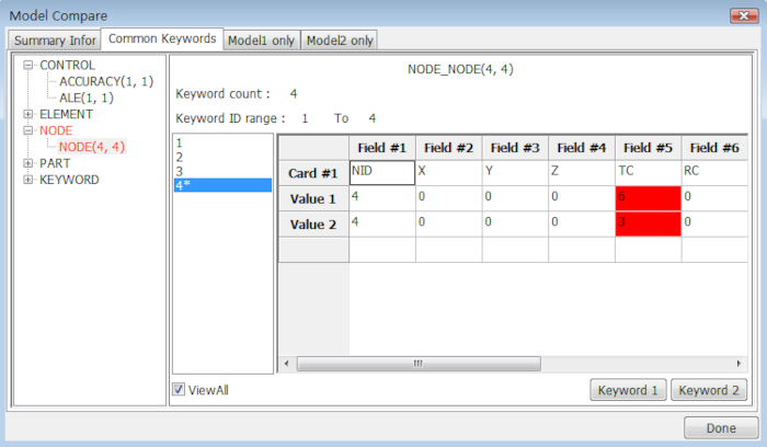
- ViewAll
View all entries for this keyword on two models.
- Keyword 1
Popup original keyword form of model 1.
- Keyword 2
Popup original keyword form of model 2.
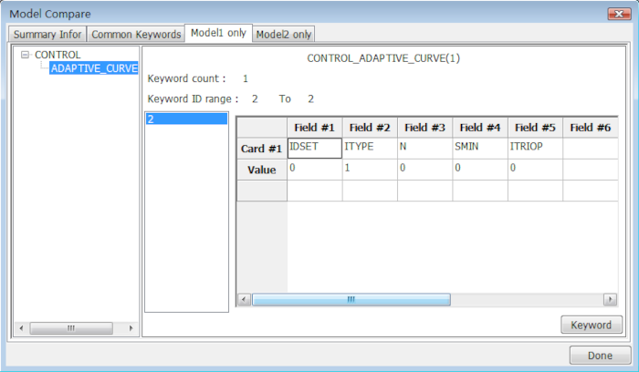
- 3. Model1 Only
List keywords just exist in model 1.
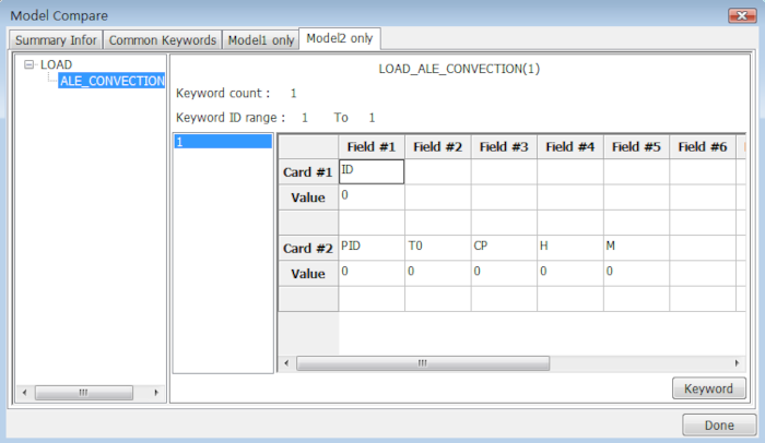
- 4. Model2 Only
List keywords just exist in model 2.
This interface provides functions for create new part, modify part property or assign new data to part.
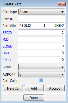
- Part type
Select part type.
- Part ID
Set part ID.
- Part title
Set part title.
- SECID
Input section ID or select section ID in popuped link dialog.
- MID
Input material ID or select material ID in popuped link dialog.
- EOSID
Input eos ID or select eos ID in popuped link dialog.
- HGID
Input hourglass ID or select hourglass ID in popuped link dialog.
- TMID
Input thermal material ID or select thermal material ID in popuped link dialog.
- GRAV
Select part initialization for gravity loading.
- ADPOPT
Select part adaptivity.
- Part Color
Set part color with Set Color Dialog.
- New ID
Set new part ID.
- Add
Add a new part with default parameters.
- Accept
Accept part data.
- Done
Exit dialog.
Set color and transparency factor for selected items. Now there are 6*7 colors defined in the color map, also user can set self-defined colors with different R, G, B values.
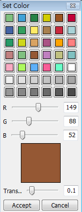
- R
Red factor value for user-defined color.
- G
Green factor value for user-defined color.
- B
Blue factor value for user-defined color.
- Trans..
User-defined transparency level.
- Accept
Apply selected color and transparency level to selected items.
- Cancel
Cancel color setting operation and exit set color dialog.
This interface supplied a general tool for keywords management.
- Keyword Edit
Include edit keyword data, keyword delete and keyword transfer.
- Keyword Search
Search keyword in current model.
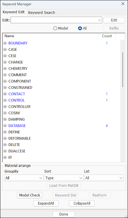
- Edit
Edit the input keyword.
- Model
Show keywords of current model.
- All
Show all keywords.
- RefBy
Show keywords which refer to selected keyword, in Keyword RefBy Dialog.
- Model Check
Model Check.
- Keyword Del
Delete selected keyword by IDs use Keyword Delete Dialog.
- ResForm
Restore all keywords using the Restore All Keyword Form dialog.
Note: Double click subitem of each kgroup will popup Keyword Form to edit keyword data.
Special control for material keywords arrange
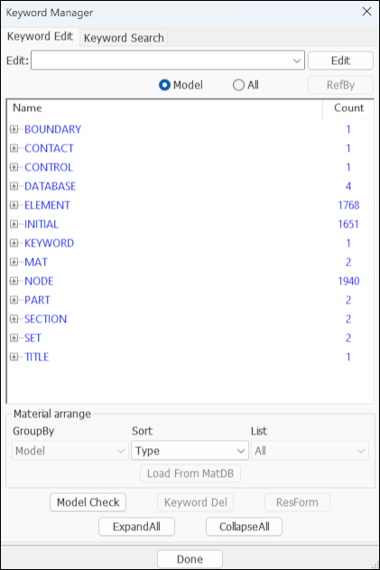
- GroupBy
Group material by element type.
- Sort
Sort material list by name or type no.
- List
List material by first character of name.
- Load From DataBase
Load from MatDB.
Menu tool for keyword management
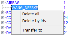
- Delete all keywords
Delete all keywords of selected keyword group use Keyword Group Delete Dialog.
- Delete all
Delete all selected keyword use Keyword Group Delete Dialog.
- Delete by ids
Delete selected keyword by ids use Keyword Delete Dialog.
- Transfer to
Transfer selected keyword to other similiar keyword use Keyword Transfer Dialog.

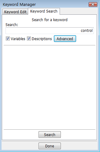
- Search
Input object for search.
- Variables
Search in variable fields.
- Descriptions
Search in Description fields.
- Advanced
More options for search.
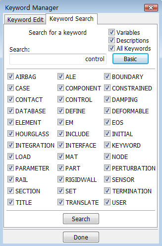
- All Keywords
Select all keywords for search.
- Basic
Basic search.
- Check box for KGroup
Checked to search in this keyword group, otherwise skip this keyword group when running search.
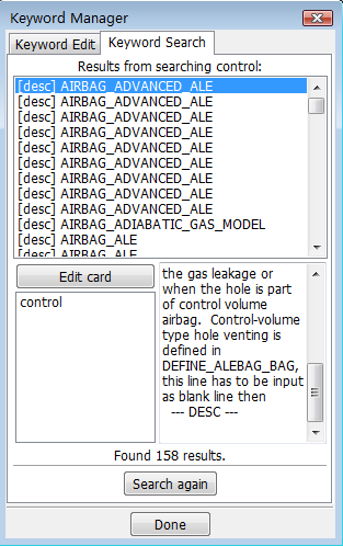
- Edit card
Read keyword data.
- Search again
Search again.
This interface used for entity data management, include display setting, creation, modification and delete.
- Spc
*BOUNDARY_SPC_NODE.
- Generalized Weld
*CONSTRAINED_GENERALIZED_WELD_SPOT.
- Spotweld
*CONSTRAINED_SPOTWELD.
- Nodal Rigid Body (CNRB)
*CONSTRAINED_NODAL_RIGID_BODY,*CONSTRAINED_NODAL_RIGID_BODY_SPC.
- Node Set
*CONSTRAINED_NODE_SET.
- Rivet
*CONSTRAINED_ RIVET.
- Tied Nodes Failure
*CONSTRAINED_TIED_NODES_FAILURE.
- Interpolation
*CONSTRAINED_INTERPOLATION and *CONSTRAINED_INTERPOLATION_LOCAL.
- Drawbead
*CONTACT_DRAWBEAD.
- Part
*DAMPING_PART_MASS and *DAMPING_PART_STIFFNESS.
- History
*DATABASE_HISTORY kind data.
- Cross Section
*DATABASE_CROSS_SECTION_SET and *DATABASE_CROSS_SECTION_PLANE.
- Box
*DEFINE_BOX,*DEFINE_BOX_ADAPTIVE and *DEFINE_BOX_COARSEN.
- Coordinate
*DEFINE_COORDINATE_NODES,*DEFINE_COORDINATE_SYSTEM and *DEFINE_COORDINATE_VECTOR.
- Vector
*DEFINE_VECTOR.
- Mass
*ELEMENT_MASS.
- Seatbelt Accelerometer
*ELEMENT_SEATBELT_ACCELEROMETER.
- Velocity
*INITIAL_VELOCITY.
- Stress Solid
*INITIAL_STRESS_SOLID
- Node
*LOAD_NODE_POINT,*LOAD_NODE_SET and *LOAD_RIGID_BODY.
- Segment
*LOAD_SEGMENT and *LOAD_SEGMENT_SET.
- Rigid Body
*LOAD_RIGID_BODY.
- Shell(Shell Set)
*.
- Rigidwall
*RIGIDWALL.
The following entities can be created using the Create Entity interface.
This interface is used to create accelerometers which in LS_DYNA are defined using the *ELEMENT_SEATBELT_ACCELEROMETER keyword card. An accelerometer is a tria element and all 3 nodes must be rigid. Rigid nodes are those belonging to a rigid body, a *CONSTRAINED_NODAL_RIGID_BODY, or extra nodes to a rigid body. Node1 of the accelerometer is defined in *DATABASE_HISTORY_NODE for outputting time histories to NODOUT and other binary time history databases. The accelerations are output in the accelerometer local coordinate system.
There are two methods for define seatbelt accelerometer data.
- Three Nodes
Create accelerometer by three nodes.
- Three Position
Create accelerometer by three position.
- Show
Show existing *ELEMENT_SEATBELT_ACCELEROMETER entities.
- Cre
Create new *ELEMENT_SEATBELT_ACCELEROMETER entities.
- Mod
Modify existing *ELEMENT_SEATBELT_ACCELEROMETER entities.
- Del
Delete existing *ELEMENT_SEATBELT_ACCELEROMETER entities.
- Label
Select label type.
- SBACID
Enter *ELEMENT_SEATBELT_ACCELEROMETER ID (unique number)..
- NewID
Generate new ID.
- IGRAV
Set value for gravitational accelerations parameter.
- INTOPT
Set value for integration option parameter.
- All
Select all *ELEMENT_SEATBELT_ACCELEROMETER entities.
- None
Deselect all *ELEMENT_SEATBELT_ACCELEROMETER entities.
- Rev
Reverse selection.
- AList
Select all entities within the selected range.
- Apply
Apply entries for creation/modification or selections for deletion.
- Cancel
Cancel this modification or selection.
Define Seatbelt Accels data by 3Nodes:
- N1/N2/N3
Pick node or enter node ID.
Define Seatbelt Accels data by 3Position:
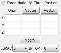
- X
Enter Origin Position X Value / X Direction / xy Plane X.
- Y
Enter Origin Position Y Value / Y Direction / xy Plane Y.
- Z
Enter Origin Position Z Value / Z Direction / xy Plane Z.
- Vector
Call Direction Dialog.
- Modify
Modify coordinates useing Coordinate Creating dialog.
This interface is for metal forming applications. It provides a facility to create binder walls for the tooling parts.
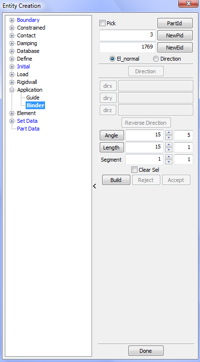
- Pick
Pick part for Binder Wall.
- PartId
Select PartID.
- NewPid
Use default new PartID.
- NewEid
Set default element starting ID.
- El_normal
Select element normal to build Binder Wall .
- Direction
Input direction to build Binder Wall.
- Direction
Call Direction Dialog to get direction.
- dirx
Set direction x for 1/-1.
- diry
Set direction y for 1/-1.
- dirz
Set direction z for 1/-1.
- Reverse Direction
Reverse direction.
- Angle
Click to reverse angle.
- Length
Input length value.
- Segment
Set total segment for generation element.
- Clear Sel
Clear current selection when building wall.
- Build
Build Binder Wall.
- Reject
Reject Binder Wall.
- Accept
Accept Binder Wall.
This interface is used for showing, creating, modifying, and deleting the following LS_DYNA keyword cards:
*CONSTRAINED_NODAL_RIGID_BODY
*CONSTRAINED_NODAL_RIGID_BODY_INERTIA
*CONSTRAINED_NODAL_RIGID_BODY_SPC
*CONSTRAINED_NODAL_RIGID_BODY_SPC_INERTIA
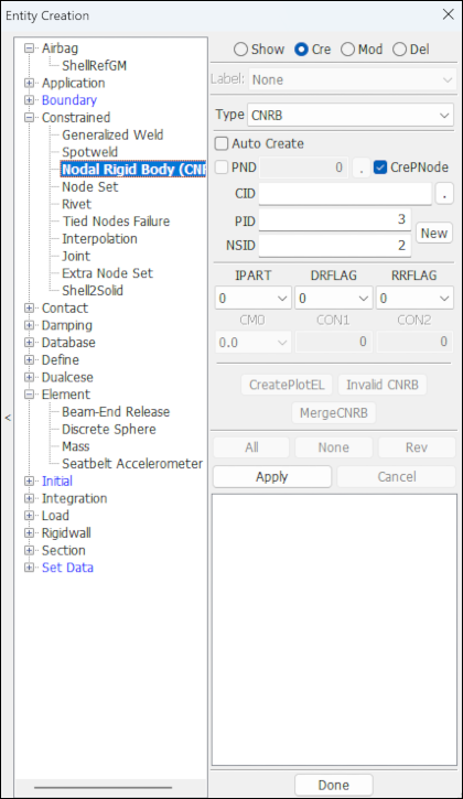
- Show
Show existing *CONSTRAINED_NODAL_RIGID_BODY entities.
- Cre
Create new *CONSTRAINED_NODAL_RIGID_BODY entities.
- Mod
Modify existing *CONSTRAINED_NODAL_RIGID_BODY entities.
- Del
Delete existing *CONSTRAINED_NODAL_RIGID_BODY entities.
- CDel
Check and delete invalid *CONSTRAINED_NODAL_RIGID_BODY.
- Label
Select label type.
- Type
Set current entity type (CNRB, CNRB_INERTIA, CNRB_SPC_INERTIA).
- Auto Create
Create CNRB when the right mouse is clicked after finish picking.
- PND
Check to pick node from model to be PNODE.
- CrePNode
Check to create PNODE at the mass center of selected nodes.
- PID
Enter Part ID of the nodal rigid body.
- CID
Enter Coordinate ID/Open link dialog by clicking on the label.
- NSID
Enter Node Set ID .
- New ID
Set PID and NSID to next highest available ID.
- PNODE
Enter PNODE/Open link dialog by clicking on the label.
- IPART
Set print flag.
- DRFLAG
Set displacement release flag.
- RRFLAG
Set rotation release flag.
- CMO
Set center of mass constraint option.
- CON1
Set first constraint parameter.
- CON2
Set second constraint parameter.
- CreatePlotEL
Create plot element with selected CNRB.
- InvalidCNRB
Select all invalid CNRB.
- MergeCNRB
Merge two or more CNRB into one CNRB.
- Apply
Apply create, delete, and modify.
- Cancel
Cancel current modification or selection.
This interface is used for showing, creating, modifying, and deleting *CONSTRAINED_NODE_SET cards in LS_DYNA.
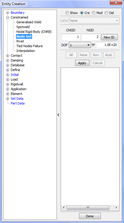
- Show
Show existing *CONSTRAINED_NODE_SET entities.
- Cre
Create new *CONSTRAINED_NODE_SET entities.
- Mod
Modify existing *CONSTRAINED_NODE_SET entities.
- Del
Delete existing *CONSTRAINED_NODE_SET entities.
- Label
Select label type.
- CNSID
Enter constrained node set ID.
- NSID
Enter Node Set ID.
- New ID
Set default new ID.
- DOF
Select degree of freedom.
- TF
Enter failure time for nodal constraint set.
- All
Select all CONSTRAINED_ NODE_SET entities.
- None
Deselect all CONSTRAINED_ NODE_SET entities.
- Rev
Reverse selection.
- AList
Select all entities within the selected range (Only applies when there are 20+ entities).
- Apply
Apply entries for creation/modification or selections for deletion.
- Cancel
Cancel this modification or selection.
Time history output requests in LS_DYNA for nodes and elements are done using the following keyword cards:
*NODES:*DATABASE_HISTORY_NODE
*BEAM:*DATABASE_HISTORY_BEAM
*SHELL:*DATABASE_HISTORY_SHELL
*SOLID:*DATABASE_HISTORY_SOLID
*TSHELL:*DATABASE_HISTORY_TSHELL
*SPH:*DATABASE_HISTORY_SPH
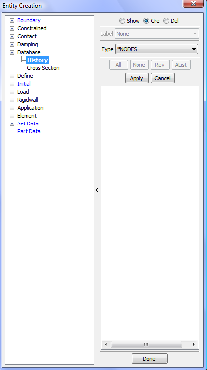
- Show
Show existing *DATABASE_HISTORY entities.
- Cre
Create new *DATABASE_HISTORY entities.
- Del
Delete existing *DATABASE_HISTORY entities.
- Label
Select label type.
- Type
Select database history data type, include NODE, BEAM, SHELL, SOLID, SPH, TSHELL.
- All
Select all *DATABASE_HISTORY entities.
- None
Deselect all *DATABASE_HISTORY entities.
- Rev
Reverse selection.
- AList
Select all entities within the selected range (Only applies when there are 20+ entities).
- Apply
Apply entries for creation/modification or selections for deletion.
- Cancel
Cancel this modification or selection.
- Write
Write selected data to file.
This interface is used for showing, creating, modifying, and deleting the following LS_DYNA keyword cards:
*DEFINE_BOX
*DEFINE_BOX_ADAPTIVE
*DEFINE_BOX_COARSEN
*DEFINE_BOX_LOCAL
The creation and modification can be carried out by various method such as selecting nodes by area, by polygon, and all visible. There are also facilities for translation and scaling.
Types of define_box data:
*Box:Define *DEFINE_BOX data. *BOX_ADAPTIVE:Define *DEFINE_BOX_ADAPTIVE data. *BOX_COARSEN:Define *DEFINE_BOX_COARSEN data. *BOX_LOCAL:Define *DEFINE_BOX_LOCAL data. Methods of define define_box data:
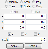
MinMax:Select two nodes as minimum and maximum for box. Area:Select nodes inside a user defined area for the box. Poly:Select nodes inside a user defined region for the box. Tran:Translate box. Scale:Scale box. Drag:Drag box(This option is currently unavailable).
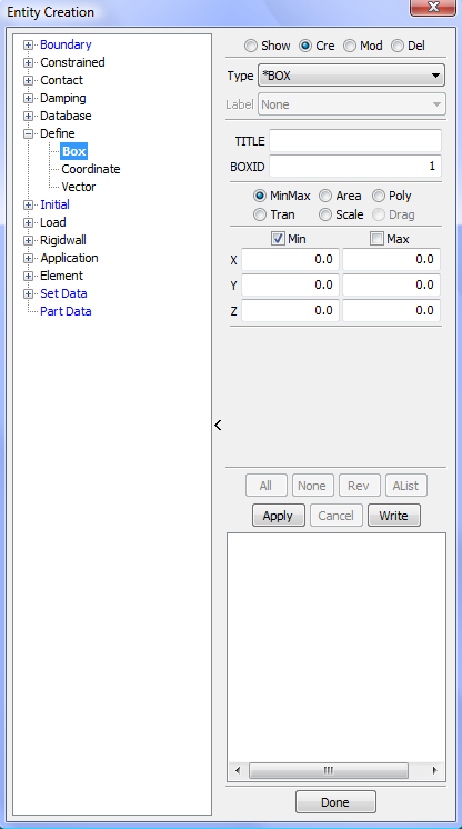
- Show
Show existing *DEFINE_BOX entities.
- Cre
Create new *DEFINE_BOX entities.
- Mod
Modify existing *DEFINE_BOX entities.
- Del
Delete existing *DEFINE_BOX entities.
- Type
Select entity type.
- Label
Set current entity label type.
- All
Select all *DEFINE_BOX entities.
- None
Deselect all *DEFINE_BOX entities.
- Rev
Reverse selection.
- AList
Select all entities within the selected range (Only applies when there are 20+ entities).
- Apply
Apply entries for creation/modification or selections for deletion.
- Cancel
Cancel this modification or selection.
- Write
Write box to file.
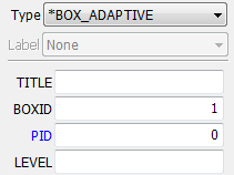
- PID
Enter PartID - If zero, all active elements are considered (only available for type: *BOX_ADAPTIVE).
- LEVEL
Maximum number of refinement levels for elements in box (only available for type: *BOX_ADAPTIVE).
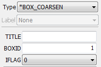
- IFLAG
Enter 0/1 (only available for type: *BOX_COARSEN).
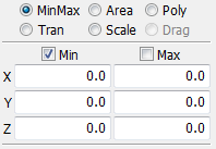
- Min
Pick node as minimum extreme of box.
- Max
Pick node as maximum extreme of box.
- X
X coordinate of min/max.
- Y
Y coordinate of min/max.
- Z
Z coordinate of min/max.
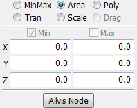
- Allvis Node
Select all visable nodes as maximum and minimum of box.
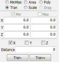
- X
Translate box in x direction.
- Y
Translate box in y direction.
- Z
Translate box in z direction.
- Distance
Enter distance to translate box.
- Tran-
Translate in negative direction.
- Tran+
Translate in positive direction.
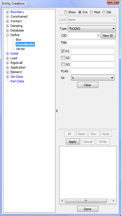
This interface is used for showing, creating, modifying, and deleting the following LS_DYNA keyword cards:
*DEFINE_COORDINATE_NODES
*DEFINE_COORDINATE_SYSTEM
*DEFINE_COORDINATE_VECTOR
- *NODES
Entity data of *DEFINE_COORDINATE_NODES.
- *SYSTEM
Entity data of *DEFINE_COORDINATE_SYSTEM.
- *VECTOR
Entity data of *DEFINE_COORDINATE_VECTOR.
- Show
Show existing *DEFINE_COORDINATE entities.
- Cre
Create new *DEFINE_COORDINATE entities.
- Mod
Modify existing *DEFINE_COORDINATE entities.
- Del
Delete existing *DEFINE_COORDINATE entities.
- Label
Set current entity label type.
- Type
Select coordinate type.
- Clear
Clear current data.
- All
Select all *DEFINE_COORDINATE entities.
- None
Deselect all *DEFINE_COORDINATE entities.
- Rev
Reverse selection.
- AList
Select all entities within the selected range (Only applies when there are 20+ entities).
- Apply
Apply entries for creation/modification or selections for deletion.
- Cancel
Cancel this modification or selection.
- Write
Write selected coord data to file.
- CID
Coordinate ID. A unique number has to be defined.
- Title
Enter box title.
- N1
Enter node ID for node at local origin.
- N2
Enter node ID for node on loacal x-axis.
- N3
Enter node ID for node on local x-y plane.
- FLAG
Set to unity, 1, if the local system is to be updated each time step for the BOUNDARY_SPC nodal constraints and ELEMENT_BEAM type 6, the discrete beam element. Generally, this option when used with nodal SPC's is not recommended since it can cause excursions in the energy balance because the constraint forces at the node may go through a displacement if the node is partially constrained.
- Dir
Axis defined by node N2 moving from the origin node N1. The default direction is the x-axis.
Use imbedded Vector Operation Interface to create system and vector data
Note: For Show, Modify, and Delete, the Entity Operation Interface will show. For Create:*SYSTEM and Create:*VECTOR, the Vector Operation Interface is embedded in the middle controls area.
This interface is for metal forming. It allows display, creation, modification, and deletion of draw beads. Drawbeads are generally created on dies to control the draw of the work piece. The inputs for creating drawbeads are generally curves from a die design group. Alternately the input can be a node set or a beam part. These node sets and beam parts are generally created using other facilities in LS-PrePost. Given the geometry of the drawbead, die part, and the blank information, this interface creates a contact definition for the drawbead in the form of a *CONTACT_DRAWBEAD keyword card.
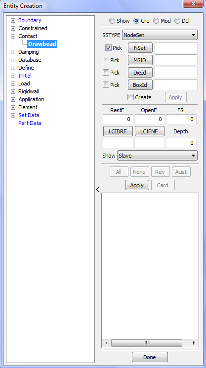
- Show
Show existing *CONTACT_DRAWBEAD entities.
- Cre
Create new *CONTACT_DRAWBEAD entities.
- Mod
Modify existing *CONTACT_DRAWBEAD entities.
- Del
Delete existing *CONTACT_DRAWBEAD entities.
- SSTYPE
Set current slave set ID type.
- NSet/Curve/PBeam
Select Slave Set .
- MSID
Select Master Set.
- DieId
Select Die.
- BoxId
Select Box.
- Create
Create box by picking nodes.
- Apply
Create new box and put ID to next field.
- RestF
Enter restraining force.
- OpenF
Enter opening force.
- FS
Enter friction force.
- LCIDRF
Enter LCIDRF value.
- LCIFNF
Enter LCIDNF value.
- Depth
Enter drawbead depth value.
- All
Select all *CONTACT_DRAWBEAD entities.
- None
Deselect all *CONTACT_DRAWBEAD entities.
- Rev
Reverse selection.
- AList
Select all entities within the selected range (Only applies when there are 20+ entities)..
- Apply
Apply entries for creation/modification or selections for deletion.
- Cancel
Cancel this modification or selection.
This interface is primarily intended for creation of guides used in metal forming analysis. Typically the mesh for a guide is built using this interface and a contact definition between the blank edge and the guide is prepared using other facilities in LS-PrePost.
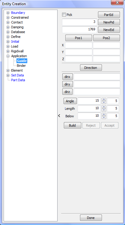
- Pick
Pick part for Guide.
- PartId
Select PartID.
- NewPid
Use default new PartID.
- NewEid
Set default element starting ID.
- Pos1
Call Position Dialog to get the first position.
- Pos2
Call Position Dialog to get the second position.
- X
Input position x value.
- Y
Input position y value.
- Z
Input position z value.
- Direction
Call Direction Dialog to get direction.
- dirx
Set direction x for 1/-1.
- diry
Set direction y for 1/-1.
- dirz
Set direction z for 1/-1.
- Angle
Reverse angle.
- Length
Input length.
- Below
Set below persent in the length.
- Build
Build guide.
- Reject
Reject guide building.
- Accept
Accept guide building.
*CONSTRAINED_GENERALIZED_WELD has many variants in LS_DYNA, but this interface is specifically for showing, creating, modifying, and deleting *CONSTRAINED_GENERALIZED_WELD_SPOT cards. Failure parameters can be set as desired and used for the welds being created. Also these parameters can be modified as necessary for each weld.
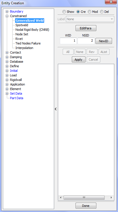
- Show
Show existing *CONSTRAINED_GENERALIZED_WELD_SPOT entities.
- Cre
Create new *CONSTRAINED_GENERALIZED_WELD_SPOT entities.
- Mod
Modify existing *CONSTRAINED_GENERALIZED_WELD_SPOT entities.
- Del
Delete existing *CONSTRAINED_GENERALIZED_WELD_SPOT entities.
- Label
Select label type.
- EditPara
Click to view and edit weld parameters.
- WID
Enter genweld optional ID.
- NSID
Enter Node Set ID.
- NewId
Set NSID to next highest, avaialble ID.
- All
Select all Constrained GWeld entities.
- None
Deselect all Constrained GWeld entities.
- Rev
Reverse selection.
- AList
Select all entities within the selected range (Only applies when there are 20+ entities).
- Apply
Apply entries for creation/modification or selections for deletion.
Click button "EditPara" to view and edit parameter of *CONSTRAINED_GENERALIZED_WELD_SPOT:
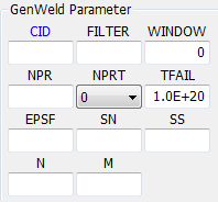
- CID
Enter coordinate system ID.
- FILTER
Enter number of force vectors saved for filtering.
- WINDOW
Enter time window for filtering.
- NPR
Enter number of individual nodal pairs.
- NPRT
Print option for RBDOUT (see LS_DYNA keyword manual for details).
- TFAIL
Enter failure time for constraint set.
- EPSF
Enter effective plastic strain at failure.
- SN
Enter normal force at failure, only for brittle failures.
- SS
Enter shear force at failure, only for brittle failures.
- N
Enter exponent for normal force, only for brittle failures.
- M
Enter exponent for shear force, only for brittle failures.
One of the most common initial conditions for crash simulations is some type initial velocity. There are some basic methods of defining initial velocity states in LS_DYNA using *INITIAL_VELOCITY and *INITIAL_VELOCITY_GENERATION, and these methods are effective for simple situations like assigning velocities to all nodes.
In contrast creating initial velocity definitions for directions other than Global XYZ can be more complex and requires additional facilities. This interface allows the flexibility to define velocities in global or local systems, along a vector, in polar coordinates, and even using a combination of angular plus translational. This interface is often used to generate initial velocity conditions for door slam, head impact, and full vehicle crash analysis.
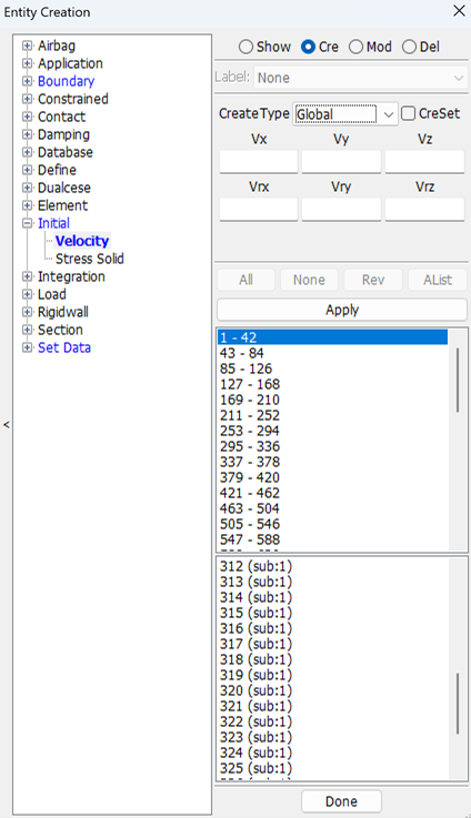
- Show
Show existing *INITIAL_VELOCITY entities.
- Cre
Create new *INITIAL_VELOCITY entities.
- CreSet
Create node set for initial velocity
- Mod
Modify existing *INITIAL_VELOCITY entities.
- Del
Delete existing *INITIAL_VELOCITY entities.
- Create Type
Set current inivel create type.
- All
Select all *INITIAL_VELOCITY entities.
- None
Deselect all *INITIAL_VELOCITY entities.
- Rev
Reverse selection.
- AList
Select all entities within the selected range (Only applies when there are 20+ entities).
- Apply
Apply entries for creation/modification or selections for deletion.
Create Type as Global:
- Vx
Enter initial velocity in x direction.
- Vy
Enter initial velocity in y direction.
- Vz
Enter initial velocity in z direction.
- Vrx
Enter initial rotational velocity in x direction.
- Vry
Enter initial rotational velocity in y direction.
- Vrz
Enter initial rotational velocity in z direction.
Create Type as Local:
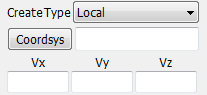
- Coordsys
Popup lind dialog to get coordsys ID.
- Vx
Enter initial velocity in x direction.
- Vy
Enter initial velocity in y direction.
- Vz
Enter initial velocity in z direction.
Create Type as AlongVect:
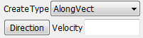
- Direction
Get Direction.
- Velocity
Enter velocity.
Create Type as Angular:
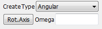
- Rot.Axis
Get position and direction.
- Omega
Enter omega.
Create Type as Ang+Tran:
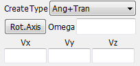
- Rot.Axis
Get position and direction.
- Omega
Enter omega .
- Vx
Enter initial velocity in x direction.
- Vy
Enter initial velocity in y direction.
- Vz
Enter initial velocity in z direction.
Create Type as Cylindrical:
- CID
Open *Define_Coordinate_kind link dialog
- Direction X/Y/Z
Which axis of CID is parallel with the z axis of coordiate system that will be created internally.
This interface is used for showing, creating, modifying, and deleting *CONSTRAINED_INTERPOLATION and *CONSTRAINED_INTERPOLATION_LOCAL cards in LS_DYNA.
INTERPOLATION:*CONSTRAINED_INTERPOLATION data edit.
INTERPOLATION_LOCAL:*CONSTRAINED_INTERPOLATION_LOCAL data edit.
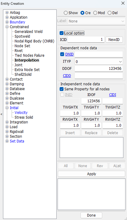
- Show
Show existing *CONSTRAINED_INTERPOLATION entities.
- Cre
Create new *CONSTRAINED_INTERPOLATION entities.
- Mod
Modify existing *CONSTRAINED_INTERPOLATION entities.
- Del
Delete existing *CONSTRAINED_INTERPOLATION entities.
- Label
Select label type.
- Local option
Check to create with _LOCAL option.
- ICID
Input interpolation constraint ID.
- NewID
Set default new interpolation id.
- DNID
Input or pick dependent node ID.
- DDOF
Input dependent degrees-of-freedom.
- ITYP
Set type of INID,0 for node id,1 for node set id.
- CIDD
Input local coordinate system ID.
- Same Property for all nodes
Check to create as all independent nodes have the same property.
- INID
Pick or input independent node ID.
- IDOF
Independent degrees-of-freedom using the same form as DDOF above.
- CIDI
Local coordinate system ID.
- TWGHTX
This weight scales the x-translational component.
- TWGHTY
This weight scales the y-translational component.
- TWGHTZ
This weight scales the z-translational component.
- RWGHTX
This weight scales the x-rotational component.
- RWGHTY
This weight scales the y-rotational component.
- RWGHTZ
This weight scales the z-rotational component.
- Insert
Insert current data group.
- Replace
Replace current data group.
- Delete
Delete current data group.
- All
Select all *CONSTRAINED_INTERPOLATION entities.
- None
Deselect all *CONSTRAINED_INTERPOLATION entities.
- Rev
Reverse selection.
- AList
Select all entities within the selected range (Only applies when there are 20+ entities).
- Apply
Apply entries for creation/modification or selections for deletion.
This interface is used for showing, creating, modifying, and deleting *CONSTRAINED_JOINT_option cards in LS-DYNA.
- Type
Type of joint to be created.
- Coord
The connection coordinates are given instead of the nodal point IDs required.
- JID
Joint ID.
- NewID
Get default new joint ID.
- Title
Joint title.
- Ni
Pick node I.
- RA
Select rigid body A.
- RB
Select rigid body B.
- RPS
Relative penalty stiffness.
- DAMP
Damping scale factor on default damping value.
- TM
Lumped translational mass.
- RM
Lumped rotational inertia.
- PARM
Parameter which a function of joint type. Leave blank for MOTORS. Gears: define R2/R1. Rack and Pinion: define h. Pulley: define R2/R1. Screw: define x/w.
- LCID
Define load curve ID for MOTOR joints.
- TYPE
Define integer flag for MOTOR joints.
- R1
Radius, R1, for the gear and pulley joint type. If left undefined, nodal points 5 and 6 are assumed to be on the outer radius.
- Local
The force output data is to be transformed into a local coordinate.
- Failure
Define failure for penalty-based joints.
- RAID
Rigid body or accelerometer ID.
- LST
Flag for local system type: EQ.0: rigid body. EQ.1: accelerometer.
- CID
Coordinate ID for resultants in the failure criteria. If zero, the global coordinate system is used.
- TFAIL
Time for joint failure. If zero, joint never fails.
- COUPL
Coupling between the force and moment failure criteria.
- NXX
Axial force resultant Nxx F at failure.
- NYY
Force resultant Nyy F at failure.
- NZZ
Force resultant Nzz F at failure.
- MXX
Torsional moment resultant Mxx F at failure.
- MYY
Moment resultant Myy F at failure.
- MZZ
Moment resultant Mzz F at failure.
- Show
Show existing joint.
- Cre
Create new joint.
- Mod
Modify joint value.
- Del
Delete joint.
- Label
Set current entity label type.
- All
Select all joint entity.
- None
Select none joint.
- Rev
Reverse selection joint.
- Alist
Select all entities within the selected range.
- Done
Close dialog.
This interface enables you to interactively show, create, modify, and delete load points and sets. It is an alternative to creating loads using Page 3 keyword cards, in that load points can be directly picked from the graphics viewport.
Node:*LOAD_NODE_POINT data edit
Set:*LOAD_NODE_SET data edit
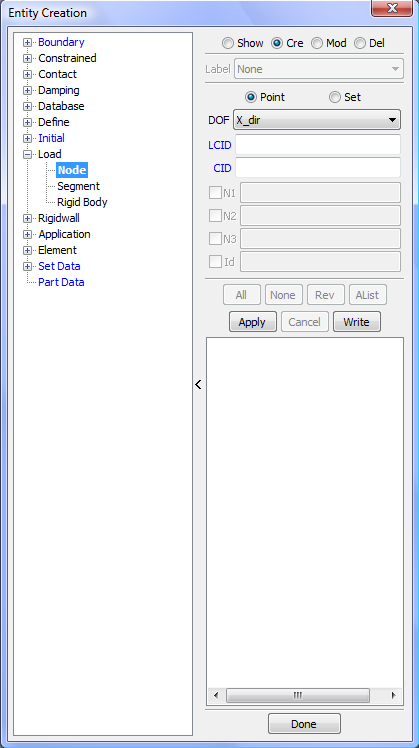
- Show
Show existing load node entities.
- Cre
Create new load node entities.
- Mod
Modify existing load node entities .
- Del
Delete existing load node entities.
- Label
Select label type.
- Node
Set current entity type as LOAD_NODE_POINT.
- Set
Set current entity type as LOAD_NODE_SET.
- DOF
Set current DOF type .
- LCID
Load Curve ID.
- CID
Coordinate System ID.
- N1
Node ID 1.
- N2
Node ID 2.
- N3
Node ID 3.
- Id
Node, Part, Node Set ID (Modify Only).
- All
Select all load node entities.
- None
Deselect all load node entities.
- Rev
Reverse selection.
- AList
Select all entities within the selected range (Only applies when there are 20+ entities).
- Apply
Apply entries for creation/modification or selections for deletion.
- Cancel
Cancel this modification or selection.
- Write
Write selected load data to file.
This interface enables you to interactively show, create, modify, and delete a load rigid body. It is an alternative to creating loads using Page 3 keyword cards in that load points can be directly picked from the graphics viewport.
*LOAD_RIGID_BODY data edit.
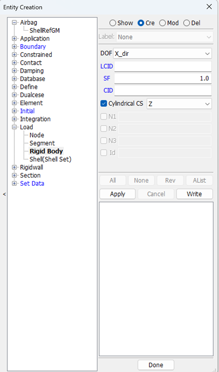
- Show
Show existing load node entities.
- Cre
Create new load node entities.
- Mod
Modify existing load node entities.
- Del
Delete existing load node entities.
- Label
Select label type.
- Rigid
Set current entity type as LOAD_RIGID_BODY.
- DOF
Set current DOF type .
- LCID
Load Curve ID.
- CID
Coordinate System ID.
- Cylindrical CS
Create point load based on cylindrical coordinate system.
- N1
Node ID 1.
- N2
Node ID 2.
- N3
Node ID 3.
- Id
Node, Part, Node Set ID (Modify Only).
- All
Select all load node entities.
- None
Deselect all load node entities.
- Rev
Reverse selection.
- AList
Select all entities within the selected range (Only applies when there are 20+ entities)..
- Apply
Apply entries for creation/modification or selections for deletion.
- Cancel
Cancel this modification or selection.
- Write
Write selected load data to file.
This interface is used for showing, creating, modifying, and deleting *LOAD_SEGMENT and *LOAD_SEGMENT_SET cards in LS_DYNA.
Load_segment : *LOAD_SEGMENT data edit.
Load_segment_set : *LOAD_SEGMENT_SET data edit.
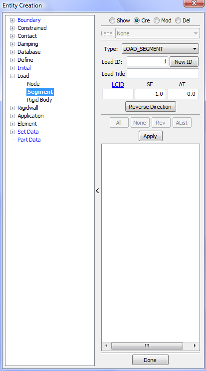
- Show
Show existing load segment entities.
- Cre
Create new load segment entities.
- Mod
Modify existing load segment entities.
- Del
Delete existing load segment entities.
- Label
Select label type.
- Type
Select load segment data type.
- Load ID
Input load data ID.
- New ID
Set defualt new ID for load data.
- Load Title
Input load data title.
- LCID
Load Curve ID.
- SF
Load curve scale factor.
- AT
Arrival time for pressure or birth time of pressure.
- SSID
Segment set ID.
- Reverse Direction
Reverse direction of load_segment.
- All
Select all load segment entities.
- None
Deselect all load segment entities.
- Rev
Reverse selection.
- AList
Select all entities within the selected range.
- Apply
Apply entries for creation/modification or selections for deletion.
This interface allows for the display, creation, modification, and deletion of *ELEMENT_MASS entities in LS_DYNA.
Edit *ELEMENT_MASS data
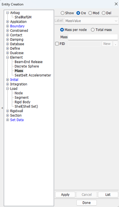
- Show
Show existing mass data.
- Cre
Create new mass data.
- Mod
Modify existing mass data .
- Del
Delete existing mass data.
- Label
Select label type.
- Mass
Enter mass value.
- Mass per node
Input mass value is assigned to each selected node.
- Total mass
Input total mass value is divided by total number of selected nodes and assigned to each one.
- Apply
Apply entries for creation/modification or selections for deletion.
- Cancel
Cancel the operation.
- List
List mass elements.
This interface is for showing, creating, modifying, and deleting the following damping definitions:
| *DAMPING_PART_MASS |
| *DAMPING_PART_STIFFNESS |
This is an alternative method to using Page 3 keyword card forms in that there is direct interaction with the model via the graphics viewport.
- Stiffness
Damping part stiffness.
- Mass
Damping part mass.
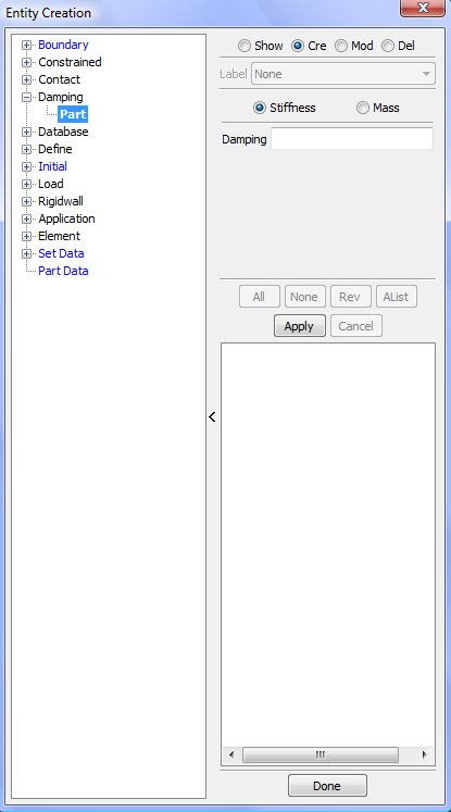
- Show
Show existing damping part nodes.
- Cre
Create new damping part nodes.
- Mod
Modify damping part value.
- Del
Delete damping part.
- Label
Select label type.
- Stiffness
Damping part stiffness.
- Mass
Damping part mass.
- Damping
Input damping value.
- All
Select all damping part entities.
- None
Deselect all damping part entities.
- Rev
Reverse selection.
- AList
Select all entities within the selected range.
- Apply
Apply entries for creation/modification or selections for deletion.
- Cancel
Cancel this modification or selection.
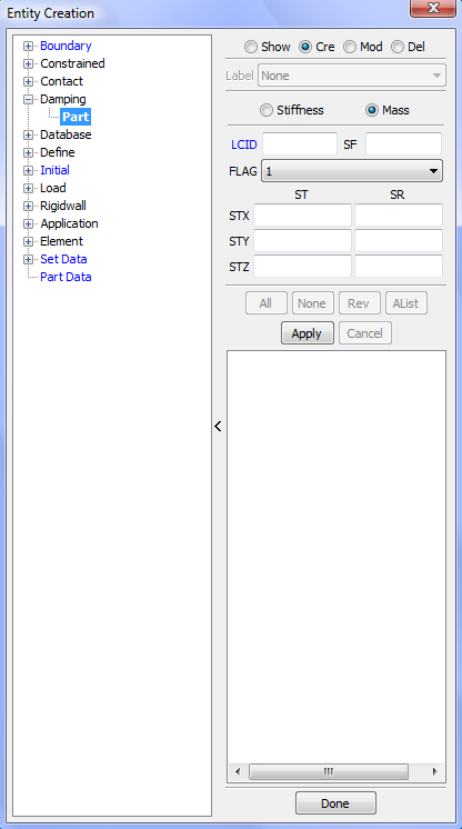
- LCID
Load curve ID which specifies system damping for parts.
- SF
Scale factor for load curve.
- FLAG
Set to unity if global components of damping forces require separate scale factors.
- ST
Scale factor on translational damping forces.
- SR
Scale factor on rotational damping moments.
- STX/Y/Z
Set X/Y/Z direction.
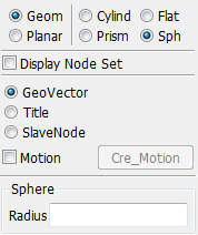
This interface is used for showing, creating, modifying, and deleting *RIGIDWALL cards in LS_DYNA. The main advantage of this interface is the ability to graphically view the various rigidwall definitions with the flexibility of positioning them using translate, rotate, and reflect functions.
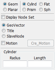
- Geom:Set geometry option.
- Cylind:
Create geometyr cylinder.
- Flat:
Create geometyr Flat.
- Prism:
Create geometyr Prism.
- Sph:
Create geometyr Sph.
- Motion:
Create slave and motion.
- Planar:
Set planar option.
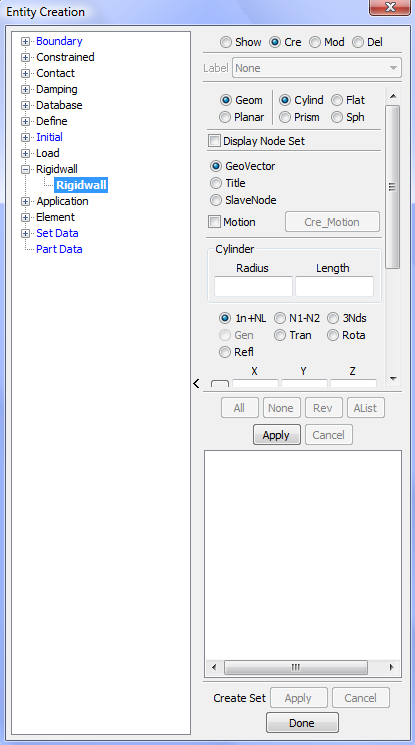
- Show
Show existing *RIGIDWALL entities.
- Cre
Create new *RIGIDWALL entities.
- Mod
Modify existing *RIGIDWALL entities.
- Del
Delete existing *RIGIDWALL entities.
- Label
Select label type.
- Geom
Set geometry option (bottom panel options shown below).
- Planar
Set planar option (bottom panel options shown below).
- Display Node Set
Display Node Set.
- GeomVector
Creat geometry.
- Title
Input para.
- SlaveNode
Create slave node.
- Motion
Set motion.
- Cre_Motion
Create motion.
- All
Select all *RIGIDWALL entities.
- None
Deselect all *RIGIDWALL entities.
- Rev
Reverse selection.
- AList
Select all entities within the selected range.
- Apply
Apply entries for creation/modification or selections for deletion.
- Cancel
Cancel this modification or selection.
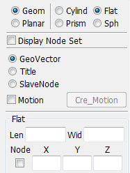
- Len
Flat length.
- Wid
Flat width.
- Node
The node for pick coordinate(flat).
- X/Y/Z
X/Y/Z-coordinate of head of edge vector l (flat).
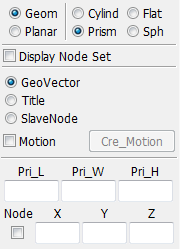
- Pri_L
Enter prism length.
- Pri_W
Enter prism width.
- Pri_H
Enter prism height.
- Node
The node for pick coordinate(prism).
- X/Y/Z
X/Y/Z-coordinate of head of edge vector l (Prism).
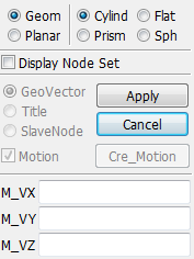
Check "Motion" and click button "Cre_Motion" to define motion data.
- Apply
Apply slave and motion.
- Cancel
Cancel create slave and motion.
- M_VX
x-direction cosine of velocity/displacement vector.
- M_VY
y-direction cosine of velocity/displacement vector.
- M_VZ
z-direction cosine of velocity/displacement vector.
This interface is used for showing, creating, modifying, and deleting *CONSTRAINED_RIVET cards in LS_DYNA.
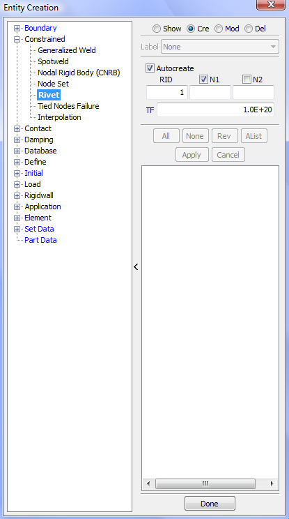
- Show
Show existing *CONSTRAINED_ RIVET entities.
- Cre
Create new *CONSTRAINED_ RIVET entities.
- Mod
Modify existing *CONSTRAINED_ RIVET entities .
- Del
Delete existing *CONSTRAINED_ RIVET entities.
- Label
Select label type.
- Autocreate
Auto create rivet.
- RID
Enter Rivet ID (Optional).
- N1
Pick/Enter node ID 1.
- N2
Pick/Enter node ID 2.
- TF
Enter failure time for nodal constraint set.
- All
Select all *CONSTRAINED_ RIVET entities.
- None
Deselect all *CONSTRAINED_ RIVET entities.
- Rev
Reverse selection.
- AList
all entities within the selected range (Only applies when there are 20+ entities).
- Apply
Apply entries for creation/modification or selections for deletion.
- Cancel
Cancel this modification or selection.
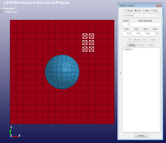
LS_DYNA uses the concept of referring to various entities through sets. There are over 60 different set types, and some of these have additional sub-types. This interface is specifically for showing, creating, modifying, and deleting some of the most common set types:
| *SET_NODE |
| *SET_BEAM |
| *SET_DISCRETE |
| *SET_PART |
| *SET_SEGMENT |
| *SET_SHELL |
| *SET_SOLID |
| *SET_TSHELL |
| *SET_SPH |
- Sample:
Show how to create SET_SEGMENT data, define other types of *SET data are all similiar to *SET_SEGMENT..
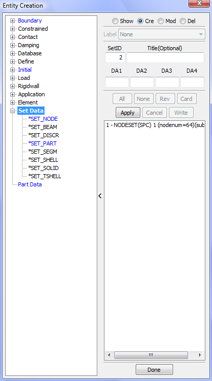
- Show
Show existing Set data.
- Cre
Create new Set data.
- Mod
Modify existing Set data.
- Del
Delete existing Set data.
- Label
Select label type.
- SetID
Enter Set ID. All node sets should have a unique set ID.
- Title
Enter title for new/current set (optional).
- DA1
Fist nodal attribute (default value is 0.0).
- DA2
Second nodal attribute (default value is 0.0).
- DA3
Third nodal attribute (default value is 0.0).
- DA4
Fourth nodal attribute (default value is 0.0).
- All
Select all sets.
- None
Deselect all sets.
- Rev
Reverse selection.
- Card
Open keyword input dialog for this set.
- Apply
Apply entries for creation/modification or selections for deletion.
- Cancel
Cancel this modification or selection.
- Write
Write selected sets to a file.
Show how to create SET_SEGMENT data.
Step 1:
Run lspp, load any .k model file that has segment elements and open data creation dialog, goto Constrained Interpolation.
Step 2:
Select Cre method.
Pick segments from the graphic view.
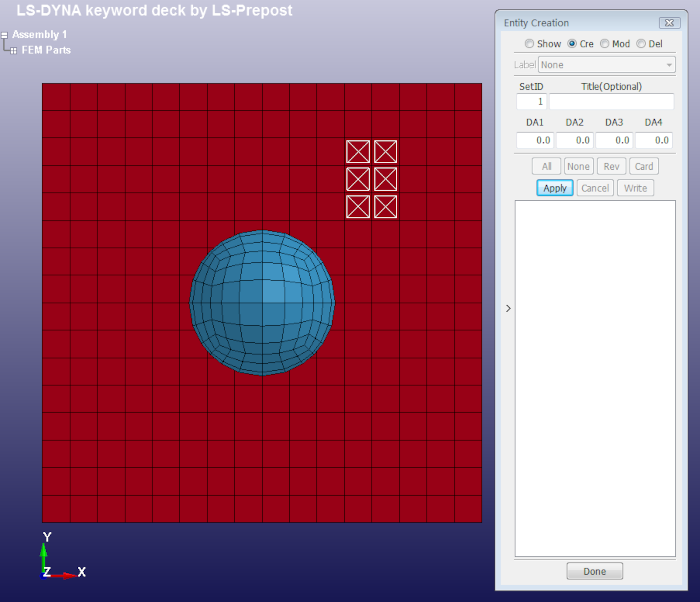
Step 3:
Click Apply to accept data create.
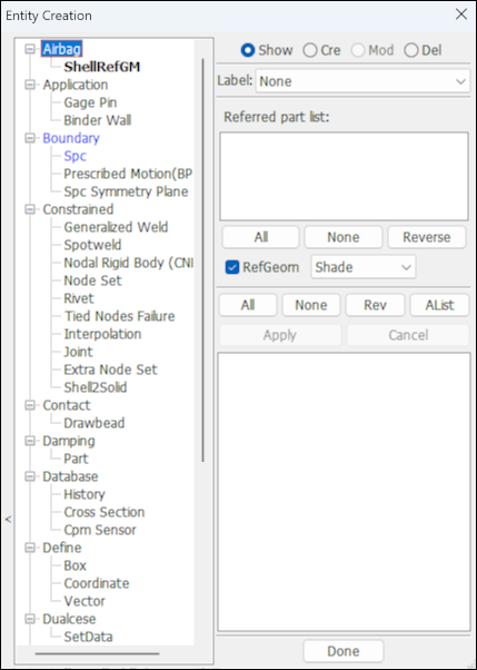
This interface is used for showing, creating, modifying, and deleting the following LS_DYNA keyword cards.
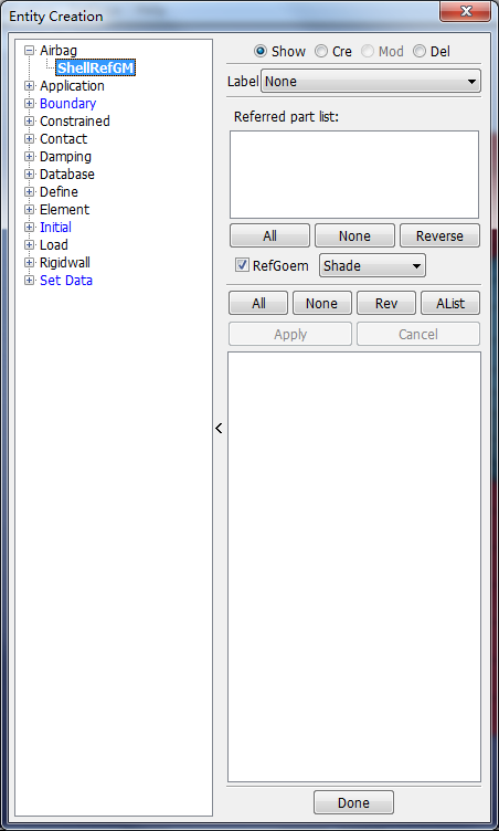
- Show
Show existing airbag shell reference geometry.
- Cre
Create new shell reference geometry.
- Mod
Modify existing shell reference geometry.
- Del
Delete shell reference geometry.
- Label
Set current entity label type.
- Referred part list
Referred parts of shell reference geometry.
- RefGoem
Display airbag reference geometry.
- Shade
Select airbag reference geometry drawing mode.
- All
Select all shell reference geometry entity.
- None
Select none shell reference geometry.
- Rev
Reverse selection shell reference goemetry.
- Alist
Select all entities within the selected range.
- Done
Close dialog.
This interface is used for showing, creating, modifying, and deleting *BOUNDARY_SPC_NODE cards in LS_DYNA.
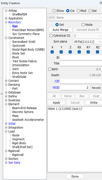
- Show
Show existing SPC nodes.
- Cre
Create new SPC nodes.
- Mod
Modify SPC value .
- Del
Delete SPC.
- Label
Select label type.
- Set
Set current for SPC set.
- Node
Set current for SPC nodes.
- AutoMerge
Merge spc conditions defined separately at same node.
- Convert NodeTR
Convert TC and RC of nodes to boundary spc and set TC and RC to 0.
- Cylindrical CS
Create SPC command based on the cylindrical coordinate system.
- Sym plane
Select symmetry plane.
- ID
ID of boundary spc keyword.
- Title
Title of boundary spc keyword.
- Birth
Check to set birth and death time for SPC.
- Death
Deactivation time for constraint.
- X
Toggle translational constraint in local X direction.
- Y
Toggle translational constraint in local Y direction.
- Z
Toggle translational constraint in local Z direction.
- RX
Toggle rotational constraint about the local X axis.
- RY
Toggle rotational constraint about the local Y axis.
- RZ
Toggle rotational constraint about the local Z axis.
- CID
Enter *DEFINE_COORDINATE_kind ID.
- NSID
Enter *DEFINE_COORDINATE_kind NSID.
- Match
Set filter to exact match.
- NewId
Set default new NSID.
- All
Select all SPC nodes.
- None
Deselect all SPC nodes.
- Rev
Reverse selection.
- AList
Select all entities within the selected range.
- Apply
Apply entries for creation/modification or selections for deletion.
- Cancel
Cancel this modification or selection.
- Write
Write selected data to file.
This interface is used for showing, creating, modifying, and deleting *CONSTRAINED_SPOTWELD cards in LS_DYNA.
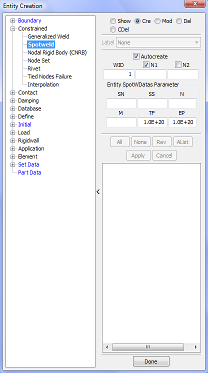
- Show
Show existing *CONSTRAINED_SPOTWELD entities.
- Cre
Create new *CONSTRAINED_SPOTWELD entities.
- Mod
Modify existing *CONSTRAINED_SPOTWELD entities.
- Del
Delete existing *CONSTRAINED_SPOTWELD entities.
- CDel
Check and delete invalid *CONSTRAINED_SPOTWELD.
- Label
Select label type.
- AutoCreate
Auto creaete spot weld.
- WID
Enter spot weld optional ID .
- N1
Enter Node ID 1.
- N2
Enter Node ID 2.
- SN
Normal force at spotweld failure (optional).
- SS
Shear force at spotweld failure (optional).
- N
Exponent for normal spotweld force (optional).
- M
Exponent for shear spotweld force (optional).
- TF
Failure time for nodal constraint set.
- EP
Effective plastic strain at failure.
- All
Select all Constrained Spotweld.
- None
Deselect all Constrained Spotweld.
- Rev
Reverse selection Constrained Spotweld.
- AList
All selected list Constrained Spotweld.
- Apply
Apply create, delete, and modify.
- Cancel
Cancel modify.
This interface is used to generate *CONSTRAINED_TIED_NODES_FAILURE definitions. These definitions are typically used for shell parts. Given a shell part or other group of shells, each shell is disjointed at all its nodes, and constraint cards are generated with user defined EPPF values.
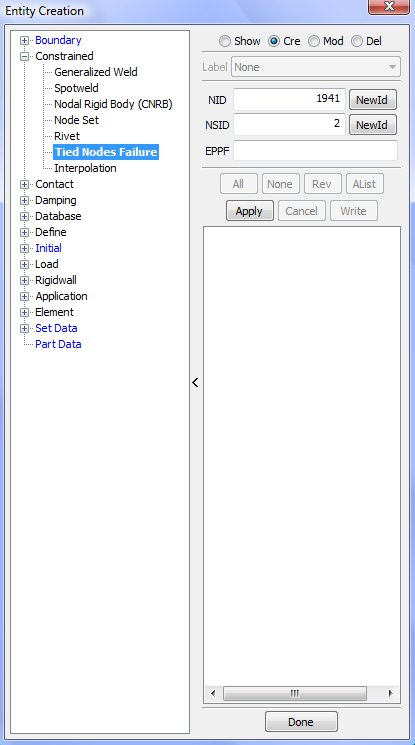
- Show
Show existing *CONSTRAINED_TIED_NODES_FAILURE entities.
- Cre
Create new *CONSTRAINED_TIED_NODES_FAILURE entities.
- Mod
Modify existing *CONSTRAINED_TIED_NODES_FAILURE entities .
- Del
Delete existing *CONSTRAINED_TIED_NODES_FAILURE entities.
- Label
Select label type.
- NID
Enter starting node ID.
- NewId
Use default starting node ID.
- NSID
Enter starting set_node ID.
- NewId
Use default starting set_node ID.
- EPPF
Enter plastic strain at failure.
- All
Select all *CONSTRAINED_TIED_NODES_FAILURE entities.
- None
Deselect all *CONSTRAINED_TIED_NODES_FAILURE entities.
- Rev
Reverse selection.
- AList
Select all entities within the selected range (Only applies when there are 20+ entities).
- Apply
Apply entries for creation/modification or selections for deletion.
- Cancel
Cancel this modification or selection.
- Write
Write selected data to file.
This interface provides a way of generating *DEFINE_VECTOR keyword cards. The definition of a vector requires xyz coordinates for both the tail and head. Various method are made available for creating a vector with options to translate, rotate, and reflect. Vectors can be shown, created, modified, and deleted through graphical interaction.
There are various methods to define vector, as the following:
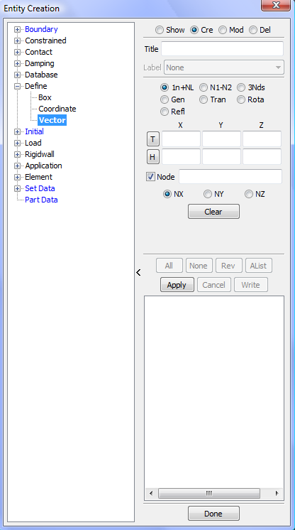
- Show
Show existing *VECTOR entities.
- Cre
Create new *VECTOR entities.
- Mod
Modify existing *VECTOR entities.
- Sear
Search for parts using user defined parameters.
- Del
Delete existing *VECTOR entities.
- Title
Set vector title (available for Create and Modify).
- All
Select all *VECTOR.
- None
Deselect all *VECTOR.
- Rev
Reverse selection *VECTOR.
- AList
Select all entities within the selected range.
- Apply
Apply entries for creation/modification.
- Cancel
Cancel this modification or selection.
- Write
Write selected vector data to file.
Note: For Show, Modify, and Delete, the Entity Operation Interface will show. For Create, the Vector Operation Interface is embedded in the middle controls area.
This interface is use to create the following cross section definitions:
*DATABASE_CROSS_SECTION_SET
*DATABASE_CROSS_SECTION_PLANE
This is an alternate method to using Page 3 keyword cards. The definition of a plane is specified through direct interaction with the model in the graphics viewport.
- Plane
Cross section data type for plane.
- Set
Cross section data type for set.
- Show
Show existing *DATABASE_CROSS_SECTION entities.
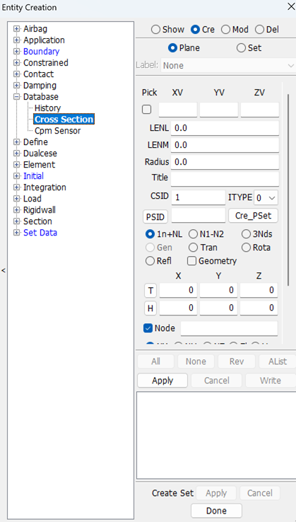
- Cre
Create new *DATABASE_CROSS_SECTION entities.
- Mod
Modify existing *DATABASE_CROSS_SECTION entities .
- Del
Delete existing *DATABASE_CROSS_SECTION entities.
- Plane
Set current section type for plane.
- Set
Set current section type for set.
- Label
Set current entity label type.
- All
Select all *DATABASE_CROSS_SECTION entities.
- None
Deselect all *DATABASE_CROSS_SECTION entities.
- Rev
Reverse selection.
- AList
Select all entities within the selected range (Only applies when there are 20+ entities)..
- Apply
Apply entries for creation/modification or selections for deletion.
- Cancel
Cancel this modification or selection.
- Write
Write selected section data to file.
Cross Plane section data:
- Pick
Pick node to set edge vector.
- XV
X-direction of head of edge vector.
- YV
Y-direction of head of edge vector.
- ZV
Z-direction of head of edge vector.
- LENL
Length of L edge .
- LENM
Length of M edge.
- Radius
Radius for circle plane.
- Title
Enter title.
- CSID
Rigid body or accelerometer ID.
- ITYPE
Flag for local system type.
- PSID
Part set ID link button.
- Cre_PSet
Create part set by genselect.
Embedded in middle portion of this panel is the Vector Operation Interface. Follow the link for a detailed description.
- CSID
Optional ID for cross section. If not specified cross section ID is taken to be the cross section order in the input deck.
- TITLE
Crowss section descriptor. It is suggested that unique descriptions be used.
- NSID
Nodal set ID, see *SET_NODE_option.
- HSID
Solid element set ID, see *SET_SOLID.
- BSID
Beam element set ID, see *SET_BEAM.
- SSID
Shell element set ID, see *SET_SHELL_option.
- TSID
Thick shell element set ID, see *SET_TSHELL.
- DSID
Discrete element set ID, see *SET_DISCRETE.
- ID
Rigid body or accelerometer ID.
- ITYPE
Flag for local system type.
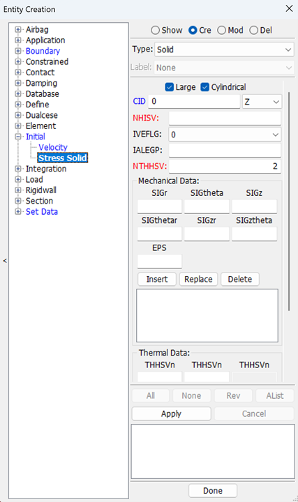
- Type
Select entity type, SOLID or SOLID_SET.
- Large
Format size, if unchecked, NHISV must also set to zero, and, if checked, a larger format is used and NHISV is used.
- Cylindrical
Check to define stress components in cylindrical coordinate system.
- CID
Reference cartesian coordinate system for the cylindrical coordinate system, 0 for global coordinate system.
- NHISV
Number of additional history variables, which is typically equal to the number of history variables stored at the integration point + IVEFLG.
- IVEFLG
Initial Volume/energy flag.
- IALEGP
The ALE multi-material group (AMMG) ID.
- NTHHSV
Number of thermal history variables per thermal integration point.
- SIGij
Define the ijth stress component.
- EPS
Effective plastic strain.
- THHSVn
nth thermal time history variable.
This interface is used for showing, creating, modifying, and deleting *LOAD_SHELL and *LOAD_SHELL_SET cards in LS_DYNA.
| SHELL_ELEMENT: *LOAD_ SHELL data edit. |
| SHELL_SET: *LOAD_ SHELL _SET data edit. |
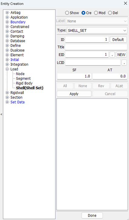
- ID
Loading ID.
- Default
Set loading id as default.
- Title
A description of the loading.
- EID
Shell element (set) ID.
- NEW
Create new shell element set.
- LCID
Load curve ID.
- SF
Load curve scale factor.
- AT
Arrival time for pressure or birth time of pressure.
This interface is used for showing, creating, modifying, and deleting keywords of:
| *BOUNDARY_PRESCRIBED_MOTION_NODE |
| *BOUNDARY_PRESCRIBED_MOTION_SET |
| *BOUNDARY_PRESCRIBED_MOTION_RIGID |
| *BOUNDARY_PRESCRIBED_MOTION_RIGID_LOCAL |
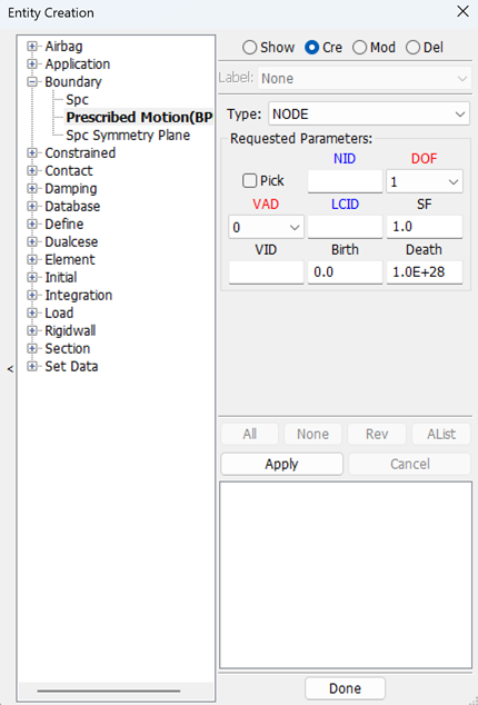
- Type
Select type of BPM.
- Pick
Check to pick nodes.
- NID
Node ID.
- DOF
Applicable degrees-of-freedom, see *BOUNDARY_PRESCRIBED_MOTION_option.
- VAD
Velocity/Acceleration/Displacement flag, see *BOUNDARY_PRESCRIBED_MOTION_option.
- LCID
Load curve ID to describe motion value versus time.
- SF
Load curve scale factor (default=1.0).
- VID
Vector ID for DOF values of 4 or 8.
- Birth
Time imposed motion/constraint is activated (default=0.0).
- Death
Time imposed motion/constraint is removed (default=1.0E+28).
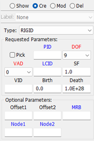
- Offset1
Offset for DOF types 9-11 (y, z, x direction).
- Offset2
Offset for DOF types 9-11 (z, x, y direction).
- MRB
Master rigid body for measuring the relative displacement.
- Node1
Optional orientation node, n1, for relative displacement.
- Node2
Optional orientation node, n2, for relative displacement.
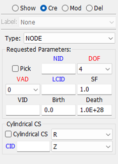
- Cylindrical CS
Create BPM command based on the cylindrical coordinate system.
- R/T
The vector direction to be created.
- CID
Id of *DEFINE_COORDINATE.
- X/Y/Z
Which axis of CID is parallel with the z axis of coordiate system that will be created internally.
This interface is used for showing, creating, modifying, and deleting keywords of *BOUNDARY_ SPC_SYMMETRY_PLANE.
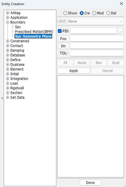
- PID
Input deformable part on which the constraints will be imposed.
- Pos
Input position of the plane.
- Dir
Input normal vector of the plane.
- TOL
Input the distance tolerance value within which the nodes on the deformable part will be constrained.
This interface is used for showing, creating, modifying, and deleting keywords of *CONSTRAINED_EXTRA_NODES_SET.
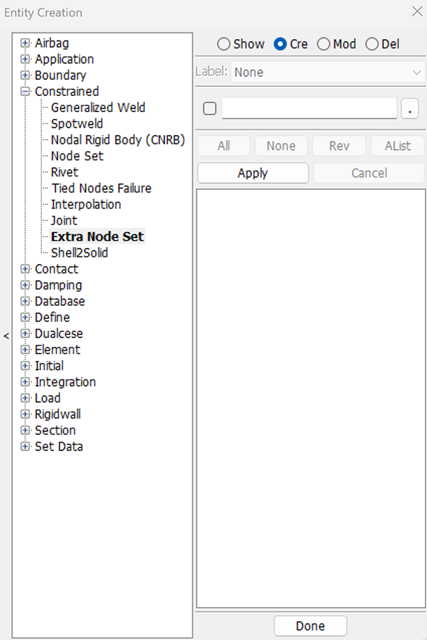
- PID
Part ID of rigid body to which the nodes are added.
This interface is used for showing, creating, modifying, and deleting keywords of *CONSTRAINED_SHELL_TO_SOLID.
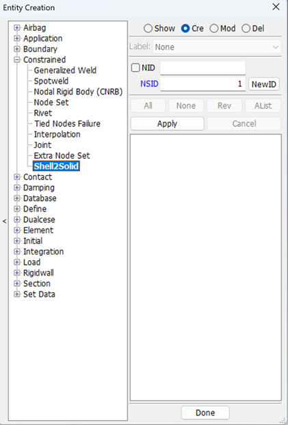
- NID
Node id on shell element.
- NSID
ID of node set.
This interface is used for showing, creating, modifying, and deleting keywords of *DATABASE_CPM_SENSOR.
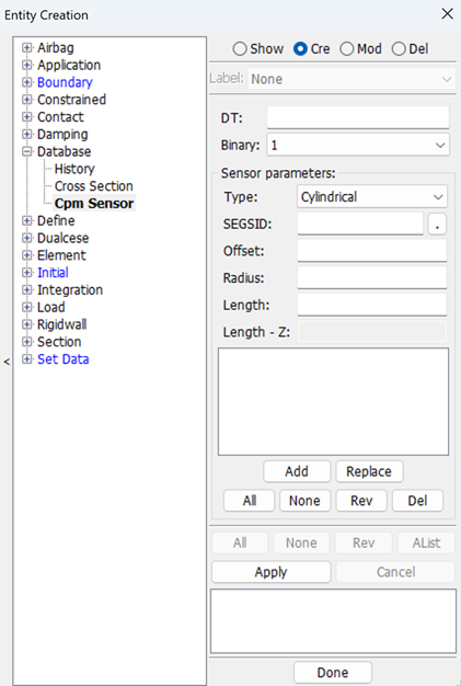
- DT
Input output interval.
- Binary
Flag for the binary file.
- Type
Select type of sensor.
- SEGSID
Input id of *SET_SEGMENT.
- Offset
Input offset distance between sensor and segment.
- Radius
Input radius of cylindrical sensor.
- Length
Input length of cylindrical sensor.
- Length – Z
Input length on z-direction of the rectangle sensor.
- Add
Add sensor data.
- Replace
Replace sensor data.
- All
Select all of the list.
- None
Deselect all of the list.
- Rev
Reverse selection of the list.
- Del
Delete selected items of the list.
This interface is used for showing, creating, modifying, and deleting keywords of *DUALCESE_NODESET, *DUALCESE_ELEMENTSET, *DUALCESE_SEGMENTSET.
- Type
Set type of DualCESE set data.
- ID
Set ID of DualCESE set data.
- New ID
Get default ID of DualCESE set data.
- Title
Set title of DualCESE set data.
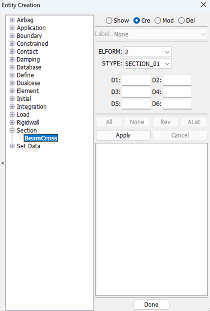
This interface is used for showing, creating, modifying, and deleting keywords of *INTEGRATION_BEAM.
- IBID
Set id of *INTEGRATION_BEAM.
- New
Generate new id for *INTEGRATION_BEAM.
- SECID
Target *SECTION_BEAM which the *INTEGREATION_BEAM will be referred by.
- ICST
Standard cross section type.
- RA
Relative area of cross section.
- K
Integration refinement parameter for standard cross section types.
- D1 – D6
Cross-section dimensions.
- SREF
Location of reference surface normal to s, for the Hughes-Liu beam only.
- TREF
location of reference surface normal to t, for the Hughes-Liu beam only.
- S
Normalized s-coordinate of integration point, -1 <= s <= 1.
- T
Normalized t-coordinate of integration point, -1 <= t <= 1.
- WF
Weighting factor.
- PID
Optional PID, used to identify material properties for this integration point.
- Insert
Insert user defined integration rule to data array.
- Replace
Replace user defined integration rule of data array.
- Delete
Delete user defined integration rule of data array.
This interface is used for showing, creating, modifying, and deleting release conditions of exist *ELEMENT_BEAM.
- RT1
Release conditions for translations at node N1.
- RT2
Release conditions for translations at node N2.
- RR1
Release conditions for rotations at node N1.
- RR2
Release conditions for rotations at node N2.
- Match
Match case, show all if all zero.
This interface is used for showing, creating, modifying, and deleting keywords of *ELEMENT_DISCRETE_SPHERE or *ELEMENT_DISCRETE_SPHERE_VOLUME.
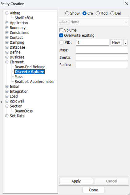
- Volume
Check to create *ELEMENT_DISCRETE_SPHERE_VOLUME.
- Overwrite existing
Check to overwrite existing discrete sphere with the same node.
- PID
Input part id of the discrete sphere element.
- New
Create new part id of the discrete sphere element.
- Mass( or Volume)
Input mass (or volume) of the discrete sphere element.
- Inertia
Input inertia of the discrete sphere element.
- Radius
Input radius of the discrete sphere element.
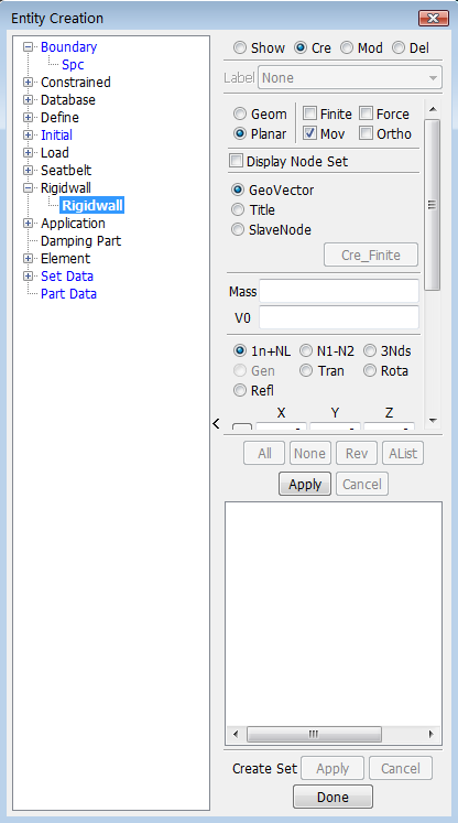
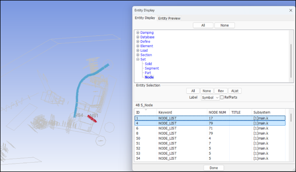
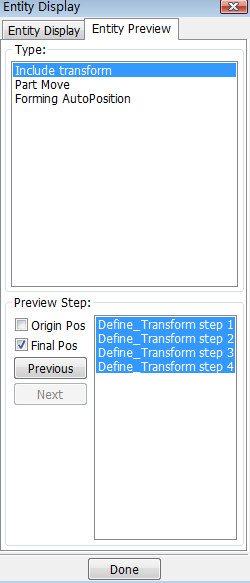
This interface is primarily a tool for entity management.
- Entity Display
Manager of entity display.
- Entity Preview
Preview of entity if it has been transformed.
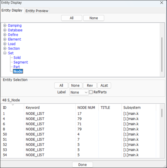
- All
Turn on all entities.
- None
Turn off all entities.
- All
Turn on all entities in the current list.
- None
Turn off all entities in the current list.
- Rev
Reverse selection.
- AList
Turn on all entities in the selected range only.
- Label
Select label type.
The software draws selected entities in different colors, so that the image is more clear.
This interface provides a means of determining how different entities within a model are related and referenced.
- Reference
Determining how entities are referenced by other entities in the model.
- Attach
Determining how parts of a complex model are physically connected to each other.
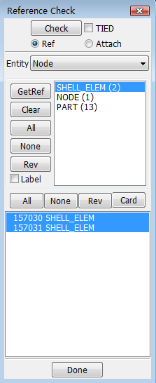
- Check
Check all referenced again.
- TIED
Set check with inipene.
- Entity
Set current refcheck entity type.
- GetRef
Get selected nodes referenced data.
- Clear
Clear selected referenced data.
- All
Select all referenced.
- None
Select none referenced.
- Rev
Reverse selection referenced.
- Label
Set entity display label.
- All
Select all referenced.
- None
Select none referenced.
- Rev
Reverse selection referenced.
- Card
Read selection referenced data by card.
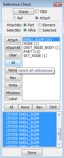
- Part
Attach by part.
- Element
Attach by element.
- AllVis
Attach by all visiable.
- Selected
Attach by selected nodes.
- Attach
Get attached nodes referenced data.
- AttachAll
Get all attach nodes referenced data.
- Clear
Clear attach.
- All
Select all referenced.
- None
Select none referenced.
- Rev
Reverse selection referenced.
- Write
Write out refdata.
- MSubsys
Move attach to new subsystem.
This interface can be used for renumbering and offsetting of entities within a model. This is only available during the pre-processing phase. An entire model can be renumbered or individual data types like nodes, materials, etc... can be renumbered and offset. For each entity type, either all or a specified range can be renumbered/offset. Upon renumbering or offsetting all referenced data will get updated by LS-PrePost.
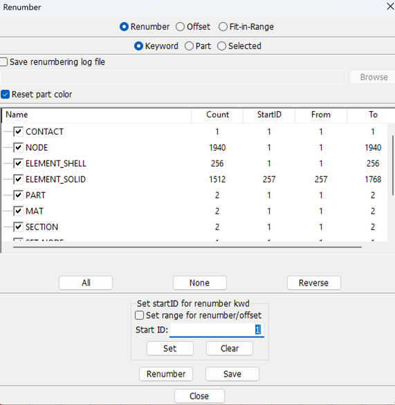
- Renumber
Renumber keyword file by user ID.
- Offset
Renumber keyword file by offset user ID.
- Fit-in-Range
Renumber keywords into target range.
- Renumber
Renumber keyword file by user ID.
- Offset
Renumber keyword file by offset user ID.
- Fit-in-Range
Renumber keywords into target range.
- Keyword
Renumber or offset keywords by selected keywords or all.
- Part
Renumber or offset nodes, elements and parts by selected.
- Selected
Renumber or offset selected nodes, shells or parts.
- Save renumbering log file
Save renumbering information to a log file.
- Reset part color
Rest part color if renumber part.
Select keywords in the tree list control, set start ids for selected keywords and range of keywords, then renumber or offset them.
- Set range for renumber/offset
Set range id in column 'from' and 'to' of the tree for renumber/offset.
- Start ID
Renumber start id/offset value ,or click the Column "StartID" of each item to edit the start id.
- SetAll
Set all the start id as the same.
- SetSel
Set start id of current selected item.
- Clear
clear current select.
- Renumber
Renumber or offset current data.
The SPlane interface is used to create section planes that can be used to perform section cuts of the model for further analysis. Various methods of cutting model cross sections are available, and the model can be animated in section cut mode.
The cross section plane can be fixed to space, fixed to the model and a lagrangian type section cutting is also available. If the model is fringed with plastic strains prior to cutting section, then the section cut will be fringed also. Model can be clipped on either side of the section plane by Off/Clip-/Clip+.
- FixS
Fixed in space means that the section plane will not move once defined.
- FixM
Fixed to Model means that the section plane can move if the nodes used to define it move.
- Lagr
Lagrangian means that a group of elements is cut initially, and then those same elements are tracked throughout the animation (and are not confined to a flat plane as the model deforms). This option is most similar to *DATABASE_CROSS_SECTION.
- 1p+NL
Define plane with 1 point and a normal. See 1p+NL sub function description.
- N1-N2
Define plane with 2 nodes (node 1 on plane, node 2 indicates normal vector). See N1-N2 sub fuction description.
- 3Nds
Define plane with 3 nodes. See 3Nds sub fuction description.
- 2Nds+D
Define plane by picking 2 nodes and a direction cosine. See 2Nds+D sub function description.
- Base Pt. Location
Dynamic display of base point coordinate(Xpos/Ypos/Zpos).
- No.of Cuts
Enter number of cuts to make/distance to move plane along the normal.
- Upd Bspt
Update base point with the current position.
- Left Arrow
Step 1 increment back.
- MP Anim
Animate moving plane along the normal.
- Right Arrow
Setp 1 increment forward.
- Clr Kpsc
Clear kept section cuts in memory.
- Project View
View section cut normal to section plane.
- Clipping Mode
Choose clipping mode (Off/Clip+/Clip-).
- Kp Cuts
Keep and display all section cuts.
- Clr
Clear all section cuts.
- Cut
Cut the section.
- Options
Other options for section plane. See Options sub function description.
- Crush
Plot intrusions relative to a plane. See Crush sub function description.
- Model
Draw normal model.
- Meas
Active section cut measure interface. See Meas sub function description.
- Line
Active section cut line plot interface. See Line sub function description.
- Force
Open section force plot interface. See Force sub function description.
- Save
Activesave plane and cut interface. See Save sub function description.
- Done
Exit section plane interface.
- BasePt
Define base point by entering x, y, z coordinates.
- BaseNd
Define base point by picking/entering a node ID.
- X/Y/Z
Enter base point x/y/z-coordinate.
- Node
Enter node number for base point.
- NormX/NormY/NormZ
Set x/y/z-component of normal vector to 1. (User also has the option to manually enter the x,y and z-components in the fields provided).
- Centroid
Use centroid of model as base point.
- CG
Use center of gravity of model as base point.
- Reset
Clear base point and normal settings.
- Node1/Node2/Node3
Enter or pick Node1/Node2/Node3.
- DcosX/DcosY/DcosZ
Enter X/Y/Z directional cosine component.
- Reset
Clear base point and normal settings.
This sub-panel allows changing color and with of section cut lines, projecting the section cut to true view and turning part thickness and vector plotting of element quantities at section level. Section cuts can be exported in various formats.
- ShowPI
Show section plane with model.
- 3DOutline
Show 3D model outline with section.
- ShMesh
Show section plane as mesh.
- Show Edge
Show edge of section.
- Line Width
Set section cut line width.
- Line Color
Set section cut line color.
- Color/Cut
Use different color for each section cut.
- Thickness
Draw section cut with thickness.
- VP
Draw vector n section cut.
- X/Y/Z
The X/Y/Z component of vector on/off.
- Vector Size
Set vector size for vector point.
- Format
Choose desired output format(Keyword/VDA/IGES/Coord+V).
- State
Enter state number for the section data to be written.
- Add Cut
Add cut to current geometry database.
- Write
Start writing section data to file.
- Curr State
Write section data for current state.
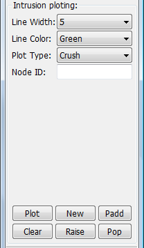
Allows plotting crush of a point in the model with respect to a plane. This plane can be fixed to space or moving with the model.
- Line Width
Select intrusion plotting line width.
- Line Color
Select intrusion plotting line color.
- Plot Type
Select histroy plot type.
- Node ID
Enter or pick a node ID to compute intrusion.
- Plot
Plot intrusion line data in current XY-Plot window.
- New
Plot intrusion line data in a new XY-Plot window.
- Padd
Add intrusion line data to current XY-Plot window.
- Clear
Clear picked/entered node IDs.
- Raise
Raise all open XY-Plot windows.
- Pop
Open and raise all closed XY-Plot windows.
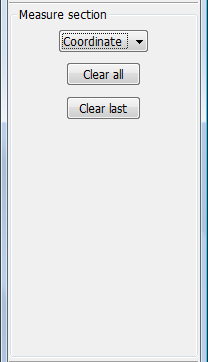
Various measurements methods are available on section cuts: coordinate, distance, 3pt-angle, 3pt-radius and 2ln-angle. Although the main application for this is for metal forming simulations, it has wide range of applications in other fields.
- Coordinate
Choose quantity to be measured.
- Clear all
Clear all measured highlight.
- Clear last
Clear last picked position.
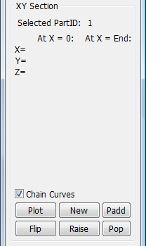
Section cut line plotting allows for plotting section properties (like shell thickness) on xy-plots. x-axis on the xy-plot is the length of the section cut line developed to a straight line. The main application of this is in metal forming simulations.
- Chain Curves
Chain broken curves into 1 single curve.
- Plot
Plot section distance vs fringe component in current XY-Plot window.
- New
Plot section distance vs fringe component in a new XY-Plot window.
- Padd
Add section distance vs fringe component data to current XY-Plot window.
- Raise
Raise all open XY-Plot windows.
- Pop
Open and Raise all closed XY-Plot windows.
- Flip
Flip the XY curve in the x-axis.
LS_DYNA has a facility to calculate and output section forces by user defining *DATABASE_CROSS_SECTION. This interface allows sections to be defined interactively and LS-PrePost computes the section quantities if shell resultants are available in d3plot files. Generally this data is available in d3plot files unless it is turned off by the use of *DATABASE_EXTENT_BINARY options.
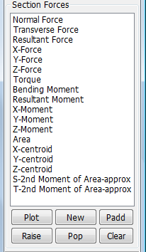
- Menu List
Select items for plotting.
- Plot
Plot section variable vs time in current XY-Plot window.
- New
Plot section variable vs time in a new XY-Plot window.
- Padd
Add selected data to current XY-Plot window.
- Raise
Raise all open XY-Plot windows.
- Pop
Open and Raise all closed XY-Plot windows.
- Clear
Clear selected items in the list.
Section plane definitions can be saved and loaded. This allows users define sections once and save them for future model revision use. Often users want to cut a cross section on various model iterations at the same specific location.
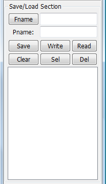
- Fname
Click to browse directory or enter filename.
- Pname
Enter name for this section definition.
- Save
Save current plane definition to buffer.
- Write
Write plane definitions from buffer to file.
- Read
Read plane definitions from file to buffer.
- Clear
Clear all plane definitions in buffer.
- Sel
Select plane definition from list as current plane.
- Del
Delete elected plane definition from buffer.
This interface allows grouping of parts of a full model to sub-systems. LS-PrePost stores the contents of each include file in sub-systems. The Create option allows for the creation of a new sub-system. Part of the model can then be moved from one sub-system to another.
- By Part
Show subsystem by part.
- By Keyword
Show subsystem by keyword.
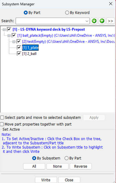
- Search
Input the object for search.
-
Search down.
-
Search down.
-
Search down.
Select parts and move to selected subsystem.
Move part properties together with part: Move part properties together with part to the new subsystem, or else move only nodes and elements.
By Subsystem: Set active by subsystem.
By Part: Set active by part.
All: Active all.
None: Active none.
Reverse: Active reverse.
Write: Write out only one subsystem(Select one subsystem).
Menu tool for subsystem management
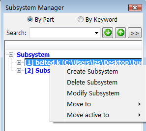
- Create Subsystem
Create new subsystem use Subsystem Property Dialog.
- Delete Subsystem
Delete selected subsystem.
- Modify Subsystem
Modify property of selected subsystem use Subsystem Property Dialog.
- Move to
Move selected items of source subsystem to target subsystem.
- Move active to
Move selected active items of source subsystem to target subsystem.
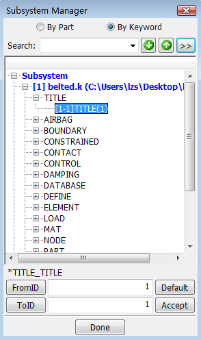
This interface is used to create and manipulate groups of parts. Often this interface is used to create groups that represent subsystems in a complex system. For example a model with two dummies, a vehicle, a deformable barrier, front seats, rear seats, etc... can be grouped. These groups can be saved to a file for later retrieval in subsequent post-processing sessions. Groups can be added to another group or subtracted form a composite group.
The grouping facility is somewhat similar to Views Interface, except here group is collection of entire parts. Its usage has similar applications in results presentation where typically a large amount of information must be conveyed to the audience in a limited time
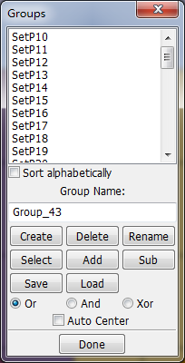
- Group Name
Enter new group name.
- Sort alphabetically
Sort group name in alphabetical order.
- Create
Create a new group from the active set.
- Delete
Delete selected group from the list.
- Rename
Re-name a selected group.
- Select
Make the selected group the active set.
- Add
Add the selected group to the active set.
- Sub
Subtract the selected group from the active set.
- Save
S ave group data to a file.
- Load
Load group data from a file.
- Done
Exit Group Operations interface.
- Or
Use OR operation for adding group.
- And
Use AND operation for adding group.
- Xor
Use XOR operation for adding group.
- Auto Center
Automatically center the selected group to screen.
This interface is used to save and retrieve information regarding model appearance, color, and orientation. It is available for both pre-processing and post-processing. Unlike the Group and SelPar interfaces, this allows storing information at an element level.
Using the Blank interface only a region of elements can be kept and stored in a view. The View interface is typically used to store various portions of a very complex model first. This information for a particular model can be stored using the Save button and later loaded using the Load button. During a presentation these views can be accessed very quickly during for time limited presentations
Various fringed information can be saved in these views such as plastic strains in one view and von-mises stress in another. While plastic strains are being animated, a view containing von-mises stress can be selected without having to go to the Fringe interface
- View
Normal view model interface.
- MPP
View MPP domain decomposition interface.
- Create
Save the current view to a view file and display in the view list.
- Select
Retrieve the selected view from the view list.
- Delete
Delete selected view from the view list.
- Save
Save the current view file to local disk.
- Load
Load a view file and display in the view list.
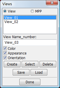
- View List
Show list of saved views.
- View Name_number
Enter new view name.
- Color
Save/Retrieve model color on/off.
- Appearance
Save/Retrieve model appearance on/off.
- Orientation
Save/Retrieve model orientation of/off.
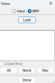
Use this interface to apply different colors and transparency levels to selected parts. This information can be saved using the Save/Retrieve Views interface.
Color interface allows user to interactively change color and transparency levels of parts. Besides changing colors of parts, following additional capabilities are available:
1. Making of a user preferred color by varying RGB levels.
2. Assigning colors to background, mesh, text, labels, highlight as well as specific color for fringe colors for each range.
Editmap allow re-definition of the colors in the Colormap grid of 6X7 colors. The user edited color map can be stored for later use using the Lmap and Smap buttons respectively.
- Color
Set color for parts.
- Transparency
Set transparency for parts.
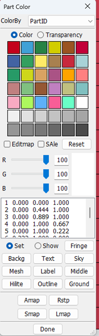
- ColorBy
Set colored by part id or material id etc.
- Color
Set color for parts.
- Transparency
Set transparency for parts.
- Color Map
Used to assign colors to parts automatically - can be used to assign colors to parts manually.
- Editmap
Clicking on the color map will assign a chosen color to the color map (toggle on/off).
- Sale
Check to set color or transparency on SALE-pre entity
- Reset
Reset the color map to default settings.
- R
Use slider/text field to set value for Red color component.
- G
Use slider/text field to set value for Green color component.
- B
Use slider/text field to set value for Blue color component.
- Color Chooser
Displays a user defined color or a color picked from a part/color map.
- Set
Assign user defined color to part/color map/option.
- Show
Show picked part/source color in the color chooser.
- Fringe
Show/set fringe color (select fringe level from list).
- Backg
Apply selected color as plain background color.
- Text
Apply selected color as text color.
- Sky
Apply selected color as sky color, (for Fade, Dia-fade and Tri-fade backgrounds).
- Mesh
Apply selected color as mesh color.
- Label
Apply selected color as label color.
- Middle
Apply selected color as middle color, (for Tri-fade background).
- Hilite
Apply selected color as highlight color.
- Outline
Apply selected color as outline color.
- Ground
Apply selected color as ground color, (for Fade, Dia-fade and Tri-fade backgrounds).
- Amap
Apply the current color map to parts.
- Rstp
Reset transparency of all parts to opaque.
- Smap
Save part colors to an ASCII file.
- Lmap
Load part colors from an ASCII file.
- Done
Exit Set Part Color interface.
The Appear interface is used to change the appearance of selected parts. This information can be saved using the Save/Retrieve Views interface.
There are certain "global" plotting modes available in the 2 rows of rendering buttons located on the bottom edge of the graphics viewport like Hide, Shade, View, etc... And these are applied to all parts in the model. In contrast, the Appear interface allows users to change plotting modes on a per part basis. This allows for entire model being in edge mode except one part in fringed mode, enabling you to compose a display that can help the audience to focus on the part of interest.
Another very important feature of this interface is to display and animate very large models using edge mode for most parts except for some of particular interest and yet have reasonable animation speeds.
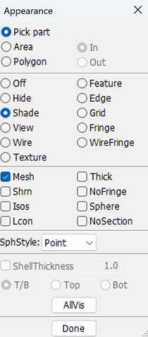
- Pick part
Assign appearance by part.
- Area
Assign appearance to parts inside/outside a user defined area.
- Polygon
Assign appearance to parts inside/outside a user defined region.
- In
Set parts inside the area/polygon.
- Out
Set parts outside the area/polygon.
- Off
No change to the part display mode.
- Hide
Display part(s) with hidden line removed.
- Shade
Display part(s) in shaded mode.
- View
Display part(s) in non-shaded color mode.
- Wire
Display part(s) in wire frame mode.
- Feature
Display part(s) in feature line mode.
- Edge
Display part(s) in edge line mode.
- Grid
Display part(s) with grid points.
- Fringe
Display part(s) with fringe.
- WireFringe
Display part(s) with mesh fringe.
- Texture
Display part(s) with mesh texture.
- Mesh
Toggle mesh outlining on/off with shad and fringe.
- Shrn
Toggle shrink plot on/off.
- Isos
Display part(s) with iso-surfaces.
- Lcon
Display part(s) with line-contours.
- Thick
Display thin shell part(s) with thickness.
- NoFringe
Display part(s) from fringe calculations.
- Sphere
Display solid part(s) as spheres.
- NoSection
Prevent Splane sectioning of parts.
- SphStyle
Select SPH sphere style.
- ShellThickness
Use default shell thickness for plotting.
- T/B
Draw Shell thickness in both top/bottom direction.
- Top
Draw Shell thickness only in top direction.
- Bot
Draw Shell thickness only in bottom direction.
- AllVis
Assign appearance to all visible parts.
- Done
Exit Set Part Appearance interface.
This interface is used to open and select multiple models during both pre-processing and post-processing. During the pre-processing phase, it allows switching of models. Translations are only for model display mode only. No permanent changes are made to the models through this interface.
Multiple model results loaded through binary files d3plot, d3thdt, d3drlf, and lspost databases can be post-processed together or individually. In order to facilitate animation of multiple models that have different termination times as well as different numbers of states, users can select whether to synchronize to the model that has the smallest state or largest.
Multiple models by default are displayed at their original position. If the user desires to move the models for side by side comparisons, translate can be use to translate models to suit the users preference.
- Model Select
Select models to be active.
- Model Translate
Translate models graphically.
- Model Remove
Remove models from the program memory.
- Model Info
Show model information.
- Model Compare
Compare two models.
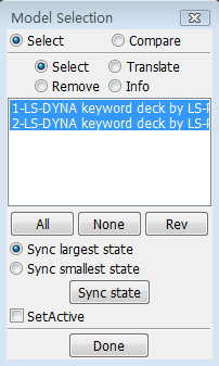
- All
Select all models to be active..
- None
Deselect all models.
- Rev
Reverse model selection.
- Sync largest states
Animate to the largest state.
- Sync smallest state
Animate to the smallest state.
- Sync state
Sync all model to the same state.
- SetActive
Select a model to make it active & pickable.
- X
Ttranslate model in global X direction.
- Y
Ttranslate model in global Y direction.
- Z
Ttranslate model in global Z direction.
- Trans Dist
The distance amount to be translated.

Translate model in negative direction

Translate model in positive direction
- Reset
Reset model to original platform
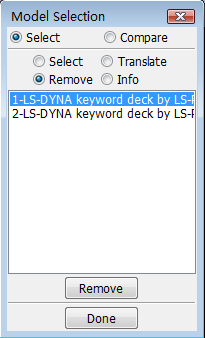
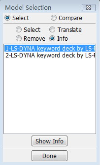
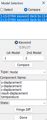
- 1st Model
First model index to be compared.
- 2nd Model
Second model index to be compared.
- Compare
Compare selected two models. See Model Compare.
This interface allows the addition of annotations to the Graphics and XY Plot windows. Annotations can be interactively added to the list or deleted from the list. Alternately, a previously defined set of annotations can be loaded through the File menu: File -> Open -> Others -> Label File.
Once an annotation label is positioned in the graphics window, it can be moved by dragging with the mouse to the desired location. Arrows originating from the annotation label to a point of interest on the graphics screen can be added to the label. These arrows can be positioned similar to the labels. Color, font, size, and angle of labels can be changed by selecting among the available options. Once the labels are positioned on the graphics area, they will remain in effect upon exiting this interface.
To remove the labels from the graphics area, labels can be deleted individually or all at once by using Delete and Reset respectively
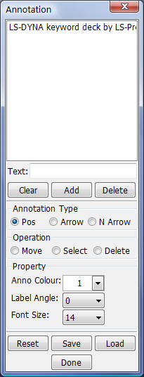
- Text
Enter new annotation text to add to list.
- Clear
Clear annotation text input field.
- Add
Add new annotation text to the list.
- Delete
Remove selected annotations from the list.
- Position
Position annotate text in drawing area.
- Arrow
Position annotate text arrow in drawing area.
- N Arrow
Position annotate arrow to a node.
- Move
Move annotate text in drawing area.
- Select
Select annotate text in drawing area.
- Delete
Delete annotation or arrows in drawing area.
- Anno Colour
Select label and arrow color.
- Label Angle
Select label angle.
- Font Size
Select label font point size.
- Reset
Delete and clear all annotations.
- Save
Save annotation file.
- Load
Load annotation file.
- Done
Exit annotation interface.
The dialog is used to split main window.
Window Configuration
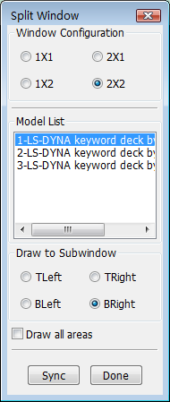
- 1X1
Single draw area. See example 1-1.
- 2X1
Split window vertically(two drawing areas). See example 1-2.
- 1X2
Split window horizontally(two drawing areas). See example 1-3.
- 2X2
Split window horizontally and verically(four drawing areas). See example 1-4.
- Model List
Select model to display in active drawing area.
- TLeft
Draw to top left drawing area. If the area had model, it will make the area activity.
- TRight
Draw to top right drawing area. If the area had model, it will make the area activity.
- BLeft
Draw to bottom left drawing area. If the area had model, it will make the area activity
- BRight
Draw to bottom right drawing area. If the area had model, it will make the area activity
- Draw all areas
Dynamic model operations will affect all drawing areas.
- Sync
Set all drawing areas (models) to state 1.
- Done
Exit Split Window interface.
This interface is used to explode/separate parts so that they can be viewed more easily. The amount of explosion can be varied by changing the factor or entering a factor in the text widget for Factor. By default the exploding of view is done in x, y, and z axes. This can be changed to only x, y, z, xy, yz, zx or xyz directions. Exploding by default is applied to all parts. This can be limited to selected parts or a group of parts. Part groups will be listed under Part Groups list if groups have been defined already. Groups can be defined using the Group Interface. Exploded display settings will be retained upon exiting the Explode interface unless cleared by Reset.
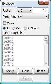
- Factor
Enter/Select an explode scale factor.
- Direction
Select directions to explode model.
- Move
Move exploded parts using mouse pointer.
- All
Move /explode all parts.
- Part
Move/explode picked parts only.
- PtGroup
Move/explode part groups only.
- Apply
Explode selected parts.
- Clear
Clear picked parts and list selections.
- Reset
Reset model.
- Done
Exit Explode Parts interface.
The Light interface is used to apply different lighting effects using up to ten independently setup lights. The appearance of the model plotted in view, shaded, or smooth shaded modes can be changed by adding lighting effects.
3 types of lighting models are available: Ambient, Diffuse, and Specular. The position of light sources and their intensity can be modified to achieve the desired effects. By default, two lights are turned on. Additional lights can be turned on/off as desired.
Once a set of lighting options are set, these setting can be saved in an LS-PrePost preferences file for future use. To save the settings, use File -> Save -> Save Configuration. This information will be written to .lspostrc in the working directory.
- Light
Interface to adjust lights.
- Material
Interface to adjust material.
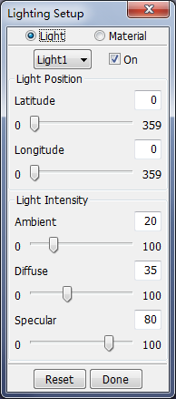
- Light
Select light.
- On
Turn highlighted light on/off.
- Latitude
Set light latitude position.
- Longitude
Set light longitude position.
- Ambient
Set light ambient.
- Diffuse
Set light diffuse.
- Specular
Set light specular.
- Reset
Reset selected light/material to default setting.
- Done
Close light dialog.
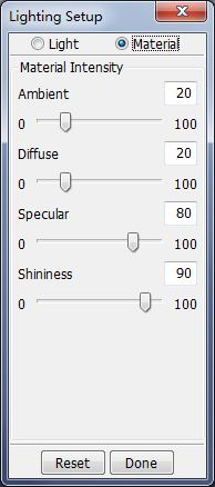
This interface is used to operate the part data.
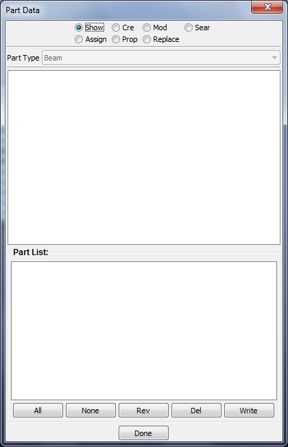
- Show
Show existing part data.
- Cre
Create new part data.
- Mod
Modify existing part data.
- Sear
Search for parts using user defined parameters.
- Assign
Assign entered data to selected part.
- Prop
Edit part property.
- Replace
Replace part.
- All
Select all parts.
- None
Deselect all parts.
- Rev
Reverse selection.
- Del
Delete selected parts.
- Write
Write selected parts to a file.
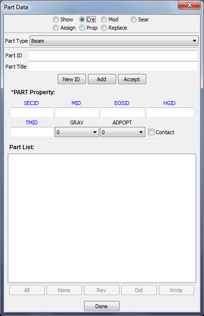
- Part Type
Select part entity type.
- Part ID
Enter part ID.
- Part Title
Enter part title.
- New ID
Generate a new ID for keyword.
- Add
Generate a new ID for keyword and set all fields to default values.
- Accept
Accept entries for current part.
- SECID
Enter section ID/Open link dialog by clicking on the lable.
- MID
Enter material ID/Open link dialog by clicking on the lable.
- EOSID
Enter equation of state ID/Open link dialog by clicking on the lable.
- HGID
Enter Hourglass/ bulk viscosity ID/Open link dialog by clicking on the lable.
- TMID
Enter thermal material property ID.
- GRAV
Select part initializaiton for gravity loading.
- ADPOPT
Select part adaptivity.
- Contact
Select to create *PART_CONTACT.
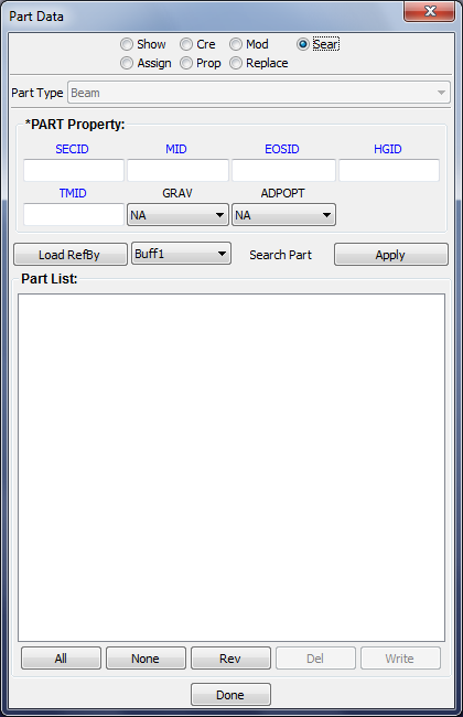
- SECID
Enter section ID/Open link dialog by clicking on the lable.
- MID
Enter material ID/Open link dialog by clicking on the lable.
- EOSID
Enter equation of state ID/Open link dialog by clicking on the lable.
- HGID
Enter Hourglass/ bulk viscosity ID/Open link dialog by clicking on the lable.
- TMID
Enter thermal material property ID.
- GRAV
Select part initializaiton for gravity loading.
- ADPOPT
Select part adaptivity.
- Load RefBy
Load part IDs stored in selected reference buffer.
- Buff1
Select buffer to load part IDs.
- Apply
Search for parts using user defined parameters.
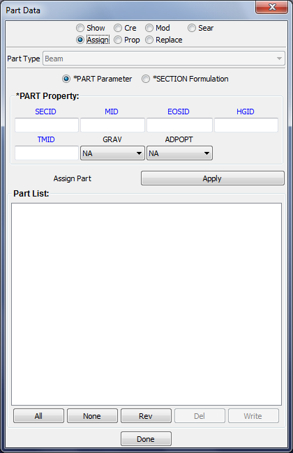
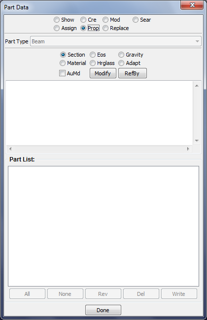
- Section
Give the section form.
- Eos
Give the Eos form.
- Gravity
Give the part form.
- Material
Give the material form.
- Hrglass
Give the hourglass form.
- Adapt
Give the part form.
- AuMd
Auto modify part IDs reference this property.
- Modify
Modify current property form data.
- RefBy
Show part IDs reference this property.
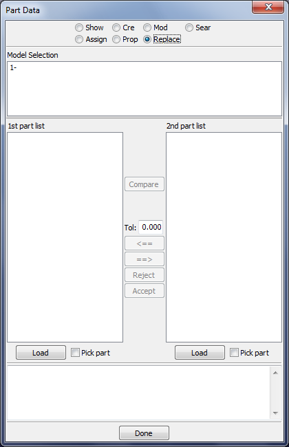
- Model Selection
Click to select moving model to 1st or 2nd list.
- 1st part list
Part list of 1st model.
- 2nd part list
Part list of 2nd model.
- Tol
Enter replace part tolerance.
- Load
Load a new model.
- Pick part
Toggle to pick part to do replace.