The following sections demonstrate how to use finite element tools to complete specific tasks.
A sample to show how to detach shells by element.
Step 1:
Go to the Detach dialog.
Step 2:
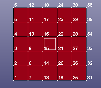
Pick the element(s) that you would like to detach(to express the meaning more clearly, all the visible nodes are identified by Identify ahead of schedule).
Step 3:
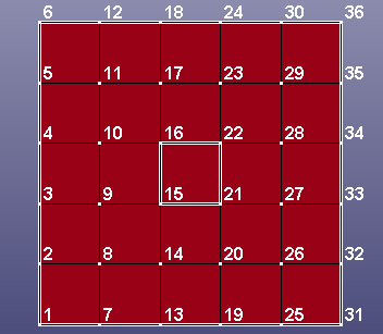
Click Detach,Accept , toggle Free Edge , you will find the edges of picked element(s) become the Free Edge .
Step 4:
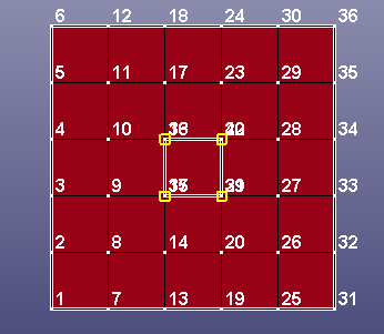
Go to the Identify dialog to identify all visible nodes again, then go to the DupNode dialog, click Show Dup Nodes , you will find four newly created duplicated nodes.
Comments:
In combination with the General Selection Interface, LS-PrePost detach function can detach shell, solid, tshell, beam elements and nodes, create newly nodes and free egdes after detaching, also, it plays a significant role for creating keyword *CONSTRAINED_TIED_NODES_FAILURE or *CONSTRAINED_TIE_BREAK.
A sample to show how to measure angle with four points. the operations of these items are similar such as Coordinate, Dist N2N, Dist N2S, Dist P2P, Angle 3Node, Angle 4Node, 3Pt Radius, Area, Volume, Mass, Inertia and Ang Vel.
LS-Prepost can measure between two models.
Step 1:
Load a d3plot file. Go to the measure dialog. Select "Angle 4Node" in items choice.
Step 2:
Pick four points orderly on the model, like this.
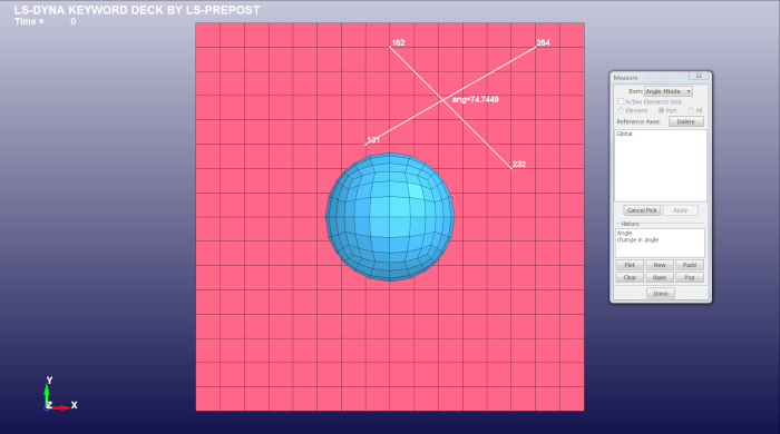
You may also input the node IDs to measure the angle.
Step 3:
The picked points can be cancel with "Cancel Pick" botton. Also, all of the picked points on the models can be clear with "Clear" botton. (It's not necessary, you can skip this step depond on requests.)
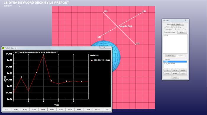
Step 4:
Select the component in "History" list, click "Plot", and then the curve changed with time will be shown in popup window.
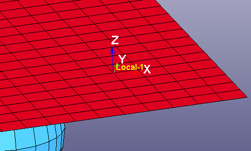
A sample to show how to create local coodinate system.
Step 1:
Set local system type to Cartesian with "Cart", Cylinderical with "Cyl", or Spherical with "Sph". Cartesian is default.
Step 2:
Pick three points orderly on the model. Pick the first point for axes origin, the second one for direction of x axes, the third one to defind XY plane of axes.
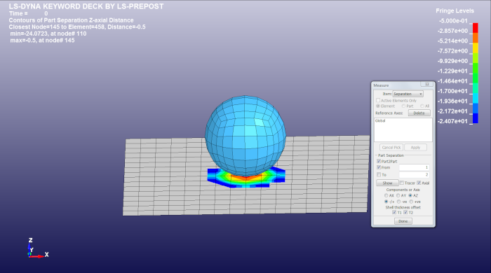
The basic idea is that you want to find the distances between two parts. The first part picked is used as the reference part, and the software takes all the nodal points for the part and projects them to the second part.
If the "Axial" box is checked the software does the projection of the nodes in an axial direction, x, y, or z. The default is the global directions. If other directions are required, a local system must be input, and selected.
The "Tracer" box enables lines to be drawn to show the projection and check that points land properly on the seconded part. The reference part is also fringed to highlight where the parts are closest.
When the parts are shells the "T1" and "T2" allow the inclusion of the shell thickness in the calculation. If they are not checked the distances are between the mid surface of the shells. The -/+, -ve, and +ve radio button allows the selection of the distance in both a position and negative direction, or just positive or negative direction.
The "Show" button is to execute the calculation and display the result. If the model is a d3plot when the state is changed the separation is automatically recalculated.
If only a region of a part is to be checked for separation the parts or one of the parts should be blanked to reduce the calculation to the area of interest.
If the "Part2Part" is unchecked then the reference part is projected to itself at a state entered as the second part.
If "Axial" is unchecked,then the projection is to the nearest point from the reference part nodes to the second part.
The parts can be beam, shell or solid. For solid the software tries to project only the elements that face each other, so that elements on the back of a solid view from the second part are automatically discounted.
Step 1:
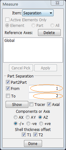
Load a d3plot file. Go to the measure dialog. Select "Separation" in items choice.
Step 2:
Pick two parts orderly on the model. The "From" and "To" text will be updated with part id, like this,
Step 3:
Select X, Y or Z axial separation distance with radion botton "AX", "AY" or "AZ". "AZ" is default.
Step 4:
Select the distance in both a position and negative direction, or just positive or negative direction with "-/+", "-ve" or "+ve". "-/+" is default.
Step 5:
Check "T1", "T2" to allow the inclusion of the shell thickness in the calculation for part1 and part2. (default is checked, just useful for shell parts)
Step 6:
Click "Show" button, the results will be render on the model, like this,
Step 7:
Check "Tracer" to enable lines to be drawn to show the projection, like this,

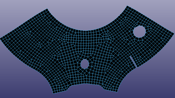
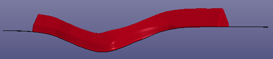
This sample demonstrates how to morph a mesh by mesh cage.
Step 1:
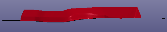
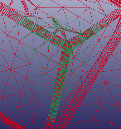
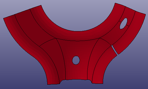
import a mesh model, rotate the mesh to be a position shown as the following picture.
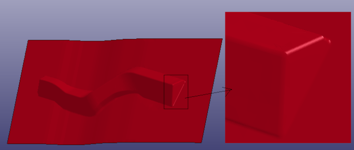
Step 2:
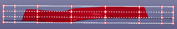
Click 'FEM->Element Tools->Morph', morph dialog will show. Select Option 'Mesh Cage'. In the element selection panel, click the radio button 'ByPart' and select the whole mesh model. Set the 'Bounding box number(x,y,z)' to be(4, 8, 4), click button 'Cage', mesh cage will be created and shown as the following picture.
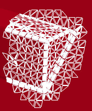
Step 3:
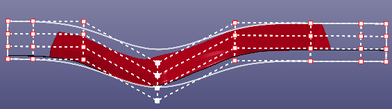
Left-mouse button clicked to select multiple cage nodes and move the selected nodes to be new position, the original mesh will be morphed concurrently.
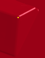
Step 4:
Check the check box 'Hide cage', the final morphed mesh is shown.
This sample demonstrates how to morph a mesh by mesh box/interior node.
Step 1:
import a mesh model, rotate the mesh to be a position shown as the following picture.
Step 2:
Click 'FEM->Element Tools->Morph', morph dialog will show. Select Option 'Mesh Box/Interior'. In the element selection panel, click the radio button 'Poly' and select a sub-mesh, then click right mouse buttton.
Step 3:
Click left mouse button to select an interior node in the sub-mesh, then click right mouse button to confirm this node.
Step 4:
Click button '+' to morph the selected sub-mesh. The morphed mesh and the original mesh are shown in the following picture.
This sample demonstrates how to unfold a 3D mesh to be a 2D mesh.
Step 1:
import a mesh mode.
Step 2:
Click 'FEM->Element Tools->Morph', morph dialog will show. Select Option 'Mesh Unfolding'. In the element selection panel, click the radio button 'ByPart' and select the whole mesh model. Click button 'Unfold', the selected mesh is flatten.