Disable the display of blocking edges and vertices.
 > >
> > Enable the display of surfaces and select Wire Frame display.
> > > Set the part parameters.
> Part Mesh Setup

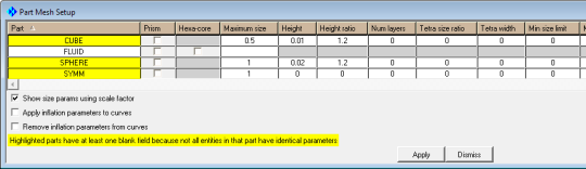
Under Maximum size:
Enter
0.5for CUBEEnter
1for both SPHERE and SYMM.
Under Height:
Enter
0.01for CUBE.Enter
0.02for SPHERE.
Under Height ratio, enter
1.2for both CUBE and SPHERE.Click and then in the Part Mesh Setup dialog box.
View the sizes set (Figure 76: Hexa Mesh Sizes).
> > Update the mesh.
> Pre-Mesh Params
 > Update Sizes
Retain the selection of Update All in the Method list.
Click .
Enable Pre-Mesh.
> The Mesh dialog box will appear, asking if you want to recompute the mesh. Click .
Disable Edges under Blocking, Surfaces and other entity types under Geometry in the display control tree.
> > Select Solid & Wire for the Pre-Mesh display.
> >
The initial mesh is shown in Figure 77: Initial Mesh.