The blocking strategy for this model involves making two internal Ogrids inside of an L shaped blocking.
The first Ogrid will capture topology, specifically to create the internal cylinder hole.
The second Ogrid will improve the mesh quality within the main elbow-pipe and provide a boundary layer.
Create the initial block.
> Create Block
 > Initialize Blocks
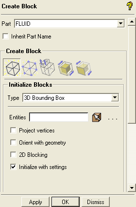
Ensure that Part is set to the correct material (FLUID).
Retain the selection of 3D Bounding Box in the Type drop-down list.
You need not select entities when creating a bounding box around the entire geometry.
Ensure that Orient with geometry is disabled.
Click to initialize the block around the entire geometry.
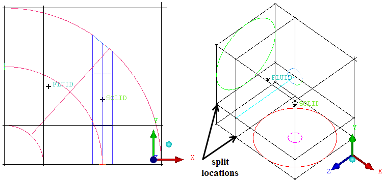
Split the initial block.
> Split Block
 > Split Block
Enable Curves in the display control tree.
Ensure that Screen select is chosen from the Split Method drop-down list.
Create splits as shown in Figure 107: Split Block by selecting any edge in the Y or X direction through which you want to run the perpendicular split.
Select the edge and hold down the left-mouse button while moving the mouse. Adjust the position such that the split is near the extent of the circular curve of the geometry. Click the middle mouse button to accept the split position.
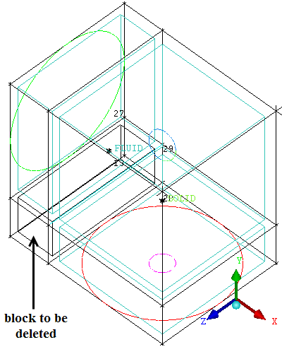
Delete the corner block.
> Delete Block

Select the block highlighted in Figure 108: Deleting the Block.
Ensure that Delete permanently is disabled and click .
Note: Deleting a block without Delete permanently enabled, will just change the material to VORFN, which is sufficient in most cases. Use Delete permanently only in rare situations where you specifically want to break up blocking topology.