> Create Body ![]() > Material Point
> Material Point ![]()
Create the FLUID material point within the volume.
Enter
FLUIDfor Part.Click
 (Select location(s)) and select two locations
on opposite sides of the elbow such that the midpoint lies within
the ELBOW_1_1 part but outside the CYL part (Figure 106: Elbow Part With Material Points).
Click the middle-mouse button to accept the selection of the points.
(Select location(s)) and select two locations
on opposite sides of the elbow such that the midpoint lies within
the ELBOW_1_1 part but outside the CYL part (Figure 106: Elbow Part With Material Points).
Click the middle-mouse button to accept the selection of the points.Click so that FLUID appears under Parts in the display control tree.
Rotate the model to confirm that the new material point is appropriate.
Similarly, create the SOLID material point inside the cylinder.
You can do this by selecting 2 locations on the edge of the cylinder.
Click to close the Create Body DEZ.
Set up mesh sizes.
> Part Mesh Setup

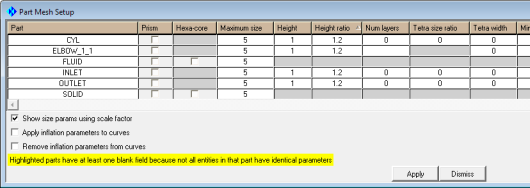
Click the Maximum size header.
The MAXIMUM SIZE dialog will appear.
Enter
5for Maximum size.Click .
Similarly set Height to
1and Height ratio to1.2.Click and then to close the Part Mesh Setup dialog box.
Note: If you enable hexa sizes (
 > > ) you can see the hexa size icon on each surface. The base size indicates the nominal size on each surface, the thickness shows the initial height at the wall (if set) and the number shows the growth ratio at the wall. Setting sizes is a quick way to seed the mesh and these hexa size icons are a quick reference to make sure the sizes are set reasonably. However precise mesh size/distribution settings should be done at the blocking level using edge parameters.
Save the geometry file (
elbow-new.tin) before proceeding with the rest of the tutorial.> >