The geometry and part information has already been defined for this tutorial. You will create the initial block in this step.
Create the initial block.
> Create Block
 > Initialize Blocks
Enter
FLUIDin the Part field.Select 2D Planar in the Type drop-down list.
Click .
Enable Vertices under Blocking.
 >
> Select Numbers under Vertices.
> > Figure 3: Initial Block shows the initial block enclosing the geometry. You will modify the initial block to create the topology of the model.
The curves are now colored separately instead of by part. This allows you to distinguish the individual curve entities from each other, which is necessary for some of the blocking operations. You can enable or disable the color coding by selecting/deselecting Show Composite.
> >
Split the initial block into sub-blocks.
In this case, you will split the initial block using two vertical splits and one horizontal split.
> Split Block
 > Split Block
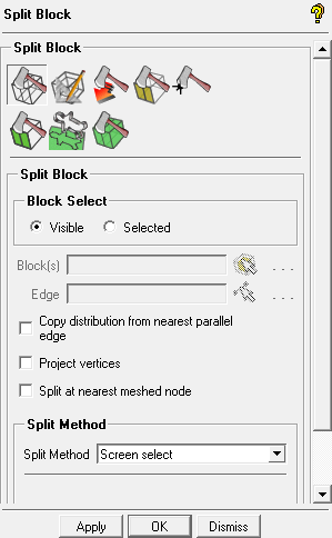
Create the vertical splits.
Ensure that Curves is enabled under Geometry.
> Retain the selection of Screen select in the Split Method drop-down list.
Note: In this case, the split may be done by approximation because only the topology of the T-shape is essential, the exact proportion is not.
Click
 (Select edge(s)) and select the edge defined by vertices 11 and 19 or by vertices 13 and 21.
Position the new edge as shown in Figure 4: Initial Vertical Split and click the middle-mouse button to accept the position.
The edge (33–34) is cyan colored indicating that it is an internal edge.
Similarly, select the edge defined by vertices 33 and 19 or vertices 34 and 21. Position the new edge (see Figure 5: Block After the Vertical Splits) and click the middle-mouse button to accept the position.
Create the horizontal split using the Relative split method.
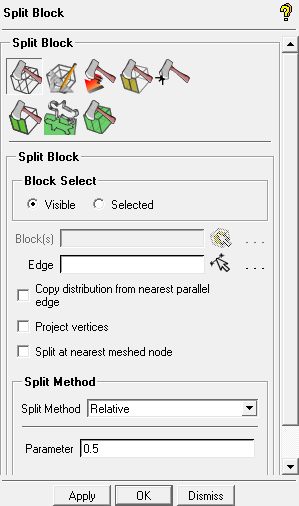
Select Relative in the Split Method drop-down list.
Enter
0.5(midpoint of selected edge) for Parameter.Select any one of the vertical edges and click .
Figure 6: Block After Three Splits shows the fully split block.
Delete the unnecessary blocks.
The next step in this “top down” approach is to remove/delete the blocks that are not required.
> Delete Blocks

Ensure that Delete permanently is disabled.
Click
 (Select block(s)) and select the blocks shown in Figure 7: Blocks to be Deleted.
Click the middle-mouse button or to accept. (See Figure 8: Blocking Topology After Deleting Blocks).
Click to remove the selected blocks.
Note: With Delete Permanent disabled (default), the deleted blocks are put into the VORFN part, a default dead zone that is usually deactivated.
The geometry and blocking of the model now resembles Figure 8: Blocking Topology After Deleting Blocks. You may need to enable Blocks, under Blocking in the Model Tree.