You will associate the edges of the blocking to the curves of the CAD geometry in this step. First select the edges and then the curves to which you want to associate them.
Note: If two or more curves are selected per operation, those curves will automatically be grouped (concatenated).
For reference, enable Show Curve Names (see Figure 9: Display Showing Vertex Numbers and Curve Names).
![]() > >
> >
This is not required for edge to curve association, but helps to illustrate the fact that each blocking edge is associated to the named curve(s).
> Associate ![]() > Associate Edge to Curve
> Associate Edge to Curve ![]()
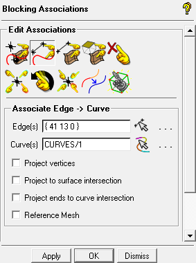
Associate the inlet, the left-most end of the large pipe.
Ensure that Project Vertices is disabled.
Click
 (Select edge(s)) and select edge 13–41. Click the middle-mouse button to accept the selection.
Click
 (Select compcurve(s)) and select CURVES/1. Click the middle-mouse button to accept the selection.
Click .
The associated edge will be colored green.
Note: If Auto Pick Mode is enabled, this operation will run in “continuation mode”, allowing you to select the next set of edges and curves without re-invoking the function. Clicking the middle mouse button when no entities are selected or clicking will cancel the function.
Similarly, associate the following edge/curve combinations to make the T fit the geometry:
Entity Edges Curves Outlet (top horizontal end of large pipe) 21-44 CURVES/7 Small pipe 33-42 CURVES/10 33-37 CURVES/11 37-43 CURVES/9 Sides of large pipe 13-34, 34-38, 38-21 CURVES/2, CURVES/5, CURVES/6 41-42, 43-44 CURVES/3, CURVES/4, CURVES/8 Note: When entities are overlapped with other entities, disabling certain entity types in the Model tree will help to identify the right entity. For example, disable Vertices and Edges to verify the curve names. Enable the Edges to proceed with the selection.
Note: For the edges defining the sides of the pipe, select all the edges first before clicking the middle-mouse button to confirm the selection. Next, select the curves, and then click the middle-mouse button again. The curves will automatically be grouped as one logical composite entity.
Verify that the correct associations have been set (see Figure 10: Association of Edges to Curves).
 > >
> > The green arrows in Figure 10: Association of Edges to Curves point from an edge to its associated curve. Nodes and vertices of these edges will project on to the associated geometry. The cyan edges (42-43, 34-42, 38-43) do not have to be associated. They are internal and will interpolate instead of project on to geometry when the mesh is computed.
Note: If the associations do not appear correctly, the edges can be reassociated to their proper curves. It is not necessary to disassociate and then reassociate. Associating the edge to a new curve will overwrite the previous association. The steps of operation can also be retraced using the Undo and Redo buttons.
Disable Show Association after verifying the associations.
> >