VM322
VM322
J-Integral Calculation for Crack in Finite Deformation-Finite Strain Hyperelastic
Solid
Overview
| Reference: | Barbieri, E., Ongaro, F., & Pugno, N.M. (2017). A J-integral-based arc-length solver for brittle and ductile crack propagation in finite deformation-finite strain hyperelastic solids with an application to graphene kirigami. Computer Methods in Applied Mechanics and Engineering, 315, 713-743. |
| Analysis Type(s): |
Static Analysis (ANTYPE = 0) NLGEOM,ON |
| Element Type(s): |
2D 4-Node Structural Solid Element (PLANE182) 2D 8-Node Structural Solid Element (PLANE183) 3D 8-Node Structural Solid Element (SOLID185) 3D 20-Node Structural Solid Element (SOLID186) |
| Input Listing: |
vm322.dat VM322 requires a supplemental .cdb input file which is too long to include full input listings. This file must be downloaded and placed in your working directory for the test case to run properly. Additionally, the geometry and mesh should be regenerated. Download link: Mechanical APDL Test Case Files for 2025 R1 vm322-1.cdb vm322-2.cdb vm322-3.cdb vm322-4.cdb |
Test Case
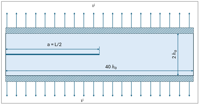
An infinitely long strip of a thin rubber sheet is shown in Figure 587 with height 2h0 and
length 40h0, where
h0 = 0.025 m. The sheet is clamped
at the top and bottom edges with an applied displacement  . An incompressible Neo-Hookean material model in plane stress with shear
modulus μ = 0.4225 MPa is used.
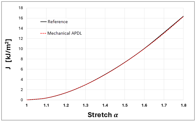
J-integral values are determined using the CINT command. The Mechanical APDL results
are then compared with those given in the reference (Figure 6, p.729).
. An incompressible Neo-Hookean material model in plane stress with shear
modulus μ = 0.4225 MPa is used.
J-integral values are determined using the CINT command. The Mechanical APDL results
are then compared with those given in the reference (Figure 6, p.729).
Figure 587: An Infinitely Long Strip of a Thin Rubber Sheet, Clamped at The Top
and Bottom Edges, with an Applied Displacement 
| Material Properties | Geometric Properties | Loading |
|---|---|---|
|
Shear modulus μ = 0.4225 MPa |
Length, L = 1000 mm Height, H = 50 mm Crack length, a = 500 mm Thickness, t = 1 mm |
Displacement
|

Analysis Assumptions and Modeling Notes
The problem is solved using 2D PLANE182 and PLANE183 with plane stress element behavior. 3D SOLID185 and SOLID186 elements with unit thickness are used. For the PLANE182 element case, full geometry is considered. Displacement is applied on the top and bottom faces in the vertical direction, and horizontal DOF is constrained. For all other elements (PLANE183, SOLID185, and SOLID186), only half the geometry is modeled and the symmetry boundary condition is used. Displacement is applied on the top surface so the model is subjected to tensile stress. The J-integral for the crack tip nodes is computed using the CINT commands. Figure 588 and Figure 589 show the contours of the final deformation for full and symmetric models, respectively.
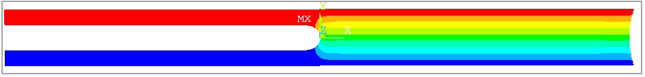
Figure 589: Vertical Displacement Contour at the End of Load Step in the Model with Symmetric Boundary Conditions

Results Comparison
| Results Comparison (J-Integral) | |||
|---|---|---|---|
| Elements | Target | Mechanical APDL | Ratio |
| PLANE182 |
16.40 | 16.31 | 1.006 |
| PLANE183 | 16.34 | 1.003 | |
| SOLID185 | 16.35 | 1.003 | |
| SOLID186 | 16.75 | 0.979 | |
The variation of the J-integral with respect to the applied stretch α using PLANE182 element is plotted in Figure 590 and compared to the reference results where the stretch α is evaluated using
 | (322–1) |