


You can perform structural-thermoelectric or thermal-piezoelectric analyses using SOLID5, SOLID98, PLANE222, PLANE223, SOLID225, SOLID226, SOLID227, or LINK228. For detailed descriptions of the elements and their characteristics (degrees of freedom, KEYOPT options, inputs and outputs, etc.), see the Element Reference.
For coupled structural-thermal-electric analyses, you need to select the UX, UY, UZ, TEMP, and VOLT element degrees of freedom. For SOLID5 or SOLID98, set KEYOPT(1) to 0. The analysis type (structural-thermoelectric or thermal-piezoelectric) for those elements is determined by the electrical material property input (resistivity or permittivity). For PLANE222, PLANE223, SOLID225, SOLID226, and SOLID227, the analysis type is determined by KEYOPT(1). For those elements, set KEYOPT(1) to 111 for a structural-thermoelectric analysis or 1011 for a thermal-piezoelectric analysis. For LINK228, set KEYOPT(1) to 111 for a structural-thermoelectric analysis.
Table 2.27: Elements Used in a Structural-Thermal-Electric Analyses
| Elements | Effects | Analysis Types |
|---|---|---|
|
SOLID5 - 8-Node Coupled-Field Hexahedral SOLID98 - 10-Node Coupled-Field Tetrahedral |
Thermoelastic (Thermal Stress) Thermoelectric (Joule Heating) Piezoelectric |
Static Full Transient |
|
PLANE222 - 4-Node Coupled-Field Quadrilateral PLANE223 - 8-Node Coupled-Field Quadrilateral SOLID225 - 8-Node Coupled-Field Hexahedral SOLID226 - 20-Node Coupled-Field Hexahedral SOLID227 - 10-Node Coupled-Field Tetrahedral |
Thermoelastic (Thermal Stress and Piezocaloric) Thermoelastic Thermoelectric (Joule Heating, Seebeck, Peltier, Thomson)Piezoresistive |
Structural-Thermoelectric: Static Full Transient |
|
Thermoelastic (Thermal Stress and Piezocaloric) Piezoelectric |
Thermal-Piezoelectric: Static Modal Full Harmonic Full Transient | |
|
LINK228 - Coupled-Field Line | Thermoelastic (Thermal Stress and Piezocaloric) Thermoelastic Thermoelectric (Joule Heating, Seebeck, Peltier, Thomson) |
Structural-Thermoelectric: Static Full Transient |
The following related topics are available:
In addition to the steps outlined in Performing a Structural-Thermal Analysis, you need to specify electrical material properties and material properties for coupled-field effects.
Specify electrical resistivities (RSVX, RSVY, RSVZ) (MP).
The following only apply to the PLANE222, PLANE223, SOLID225, SOLID226, or SOLID227 elements:
You can specify electric permittivity (PERX, PERY, PERZ) (MP) to model transient electrical effects (capacitive effects). For more information, see Thermal-Electric Analysis.
You can specify Seebeck coefficients (SBKX, SBKY, SBKZ) (MP) to include the Seebeck-Peltier thermoelectric effects. For more information, see Thermal-Electric Analysis.
You can specify a piezoresistive matrix (TB,PZRS) to include the piezoresistive effect. For more information, see Piezoresistive Analysis.
To perform a circuit analysis, use the CIRCU124 element. (For more information, see Elements Used in Circuit Analysis in the Low-Frequency Electromagnetic Analysis Guide.)
You can specify structural nonlinear material models (TB). (See the Structural Material Properties table in the PLANE222, PLANE223, SOLID225, SOLID226, and SOLID227 element descriptions.)
In a structural-thermoelectric analysis with structural nonlinearities, you should use weak (load vector) coupling between the structural and thermal degrees of freedom (KEYOPT(2) = 1) and suppress the thermoelastic damping in a transient analysis (KEYOPT(9) = 1). When using the SOLID226 element, you should also select the uniform reduced integration option (KEYOPT(6) = 1).
The following only apply to the LINK228 element:
You can specify electric permittivity (PERX) (MP) to model transient electrical effects (capacitive effects). For more information, see Thermal-Electric Analysis.
You can specify Seebeck coefficients (SBKX) (MP) to include the Seebeck-Peltier thermoelectric effects. For more information, see Thermal-Electric Analysis.
To perform a circuit analysis, use the CIRCU124 element. (For more information, see Elements Used in Circuit Analysis in the Low-Frequency Electromagnetic Analysis Guide.)
You can specify structural nonlinear material models (TB). (See the Structural Material Properties table in the LINK228 element description.)
In a structural-thermoelectric analysis with structural nonlinearities, you should use weak (load vector) coupling between the structural and thermal degrees of freedom (KEYOPT(2) = 1) and suppress the thermoelastic damping in a transient analysis (KEYOPT(9) = 1).
See Example: Electro-Thermal Microactuator Analysis for an example problem.
In addition to the steps outlined in Performing a Structural-Thermal Analysis, you need to specify electrical material properties and material properties for coupled-field effects.
For SOLID5 or SOLID98, specify electric permittivity (PERX, PERY, PERZ) (MP). For PLANE222, PLANE223, SOLID225, SOLID226, and SOLID227, specify permittivity either as PERX, PERY, PERZ (MP) or by specifying the terms of the anisotropic permittivity matrix (TB,DPER and TBDATA). To model dielectric losses, use PLANE222, PLANE223, SOLID225, SOLID226, or SOLID227 and specify a loss tangent (MP,LSST). For more information, see Piezoelectric Analysis.
Specify the piezoelectric matrix (TB,PIEZ). For more information, see Piezoelectric Matrix.
To perform a circuit analysis, use the CIRCU94 element. For more information, see Piezoelectric-Circuit Simulation.
This example problem considers an electro-thermal microactuator described in "Comprehensive thermal modeling and characterization of an electro-thermal compliant microactuator" by N.D. Mankame and G. K. Ananthasuresh, J. Micromech. Microeng. Vol. 11 (2001) pp. 452-462.
The following topics are available:
The actuator silicon structure has a thin arm connected to a wide arm, flexure, and two anchors:
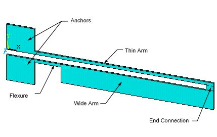
In addition to providing mechanical support, the anchors also serve as electrical and thermal connections. The actuator operates on the principle of differential thermal expansion between the thin and wide arms. When a voltage difference is applied to the anchors, current flows through the arms producing Joule heating. Because of the width difference, the thin arm of the microactuator has a higher electrical resistance than the wide arm, and therefore it heats up more than the wide arm. The non-uniform Joule heating produces a non-uniform thermal expansion, and actuator tip deflection.
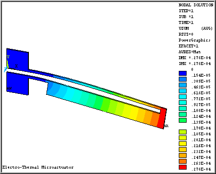
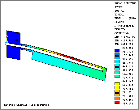
A 3D static structural-thermoelectric analysis is performed to determine the tip deflection and temperature distribution in the microactuator when a 15 volt difference is applied to the anchors. Radiative and convective surface heat transfers are also taken into account, which is important for accurate modeling of the actuator. The microactuator dimensions (device D2 in the reference) and material properties of doped single-crystal silicon used for the simulation were taken from the reference above. The temperature dependent convective heat losses were applied to all the actuator surfaces; however, they may have been applied in a different way than in the reference.
The tip deflection is determined to be 27.8 µm. The temperature ranges from 300 to 800 K. Displacement and temperature results are shown in the following figures.
/title, Electro-Thermal Microactuator
/nopr
d1=40e-6               ! Microactuator dimensions, m
d2=255e-6
d3=40e-6
d4=330e-6
d5=1900e-6
d6=90e-6
d7=75e-6
d8=352e-6
d9=352e-6
d11=20e-6

! === Loads
Vlt=15                 ! Voltage difference, Volt
Tblk=300               ! Bulk temperature, K

/VIEW,1,1,2,3
/PREP7
et,1,SOLID227,111      ! Structural-thermoelectric tetrahedron
! === Material properties
mp,EX,1,169e9          ! Young modulus, Pa
mp,PRXY,1,0.3          ! Poisson's ratio
mp,RSVX,1,4.2e-4       ! Electrical resistivity, Ohm-m
! Temperature table for ALPX and KXX
mptemp,1,300,400,500,600,700,800
mptemp,7,900,1000,1100,1200,1300,1400
mptemp,13,1500
! Coefficients of thermal expansion data table, 1/K
mpdata,ALPX,1,1,2.568e-6,3.212e-6,3.594e-6,3.831e-6,3.987e-6,4.099e-6
mpdata,ALPX,1,7,4.185e-6,4.258e-6,4.323e-6,4.384e-6,4.442e-6,4.5e-6
mpdata,ALPX,1,13,4.556e-6
! Thermal conductivity data table, W/(m-K)
mpdata,KXX,1,1,146.4,98.3,73.2,57.5,49.2,41.8
mpdata,KXX,1,7,37.6,34.5,31.4,28.2,27.2,26.1
mpdata,KXX,1,13,25.1

tref,Tblk             ! Reference temperature

! === Solid model
k,1,0,0               ! Define keypoints
k,2,0,d9
k,3,d8,d9
k,4,d8,d1
k,5,d8+d4+d5,d1
k,6,d8+d4+d5,-(d7+d2)
k,7,d8+d4,-(d7+d2)
k,8,d8+d4,-(d7+d3)
k,9,d8,-(d7+d3)
k,10,d8,-(d7+d9)
k,11,0,-(d7+d9)
k,12,0,-d7
k,13,d8+d4+d5-d6,-d7
k,14,d8+d4+d5-d6,0
a,1,2,3,4,5,6,7,8,9,10,11,12,13,14 ! Define area
vext,1,,,,,d11       ! Extrude area by the out-of-plane size

! === Finite element model
lsel,s,line,,31,42   ! Element size along out-of-plane dimension
lesize,all,d11
lsel,s,line,,1,3     ! Element size along anchor sides
lsel,a,line,,9,11
lsel,a,line,,15,17
lsel,a,line,,23,25
lesize,all,d9/2
lsel,s,line,,5       ! Element size along side walls
lsel,a,line,,19
lesize,all,(d1+d2+d7)/6
lsel,s,line,,13      ! Element size along the end connection
lsel,a,line,,27
lesize,all,d7/3
lsel,s,line,,8       ! Element size along the flexure
lsel,a,line,,22
lesize,all,d4/6
lsel,s,line,,4       ! Element size along the thin arm
lsel,a,line,,18
lesize,all,(d4+d5)/30
lsel,s,line,,14
lsel,a,line,,28
lesize,all,(d8+d4+d5-d6)/40
lsel,s,line,,7       ! Element size along the wide arm
lsel,a,line,,21
lesize,all,d2/5
lsel,s,line,,12
lsel,a,line,,26
lesize,all,(d8+d4+d5-d6)/35
lsel,s,line,,6
lsel,a,line,,20
lesize,all,d5/25
lsel,all
vmesh,1              ! Mesh the volume

! === Degree-of-freedom constraints on the anchors
nsel,s,loc,x,0,d8
nsel,r,loc,z,0       ! Bottom surface
d,all,UX,0,,,,UY,UZ
d,all,TEMP,Tblk
nsel,all

nsel,s,loc,x,0,d8
nsel,r,loc,y,-(d7+d9),-d7
cp,1,VOLT,all
n_gr=ndnext(0)
d,n_gr,VOLT,0
nsel,s,loc,x,0,d8
nsel,r,loc,y,0,d9
cp,2,VOLT,all
n_vlt=ndnext(0)
d,n_vlt,VOLT,Vlt
nsel,all

! === Radiosity boundary conditions
sf,all,RDSF,0.7,1    ! Surface-to-surface radiation load
spctemp,1,Tblk       ! Ambient temperature
stef,5.6704e-8       ! Stefan-Boltzman radiation constant, J/(K)4(m)2(s)

! === Temperature dependent convection boundary conditions
Mptemp               ! Initialize temperature table
! Temperature table for thermal loading
mptemp,1,300,500,700,900,1100,1300
mptemp,7,1500
! === Upper face
asel,s,area,,2       ! Thin arm and flexure
nsla,s,1
nsel,r,loc,x,d8,d8+d4+d5-d6
nsel,r,loc,y,0,d1
sf,all,CONV,-1,Tblk
nsla,s,1
nsel,r,loc,x,d8,d8+d4
nsel,r,loc,y,-(d3+d7),-d7
sf,all,CONV,-1,Tblk
mpdata,HF,1,1,17.8,60.0,65.6,68.9,71.1,72.6
mpdata,HF,1,7,73.2
nsla,s,1              ! Wide arm
nsel,r,loc,x,d8+d4,d8+d4+d5-d6
nsel,r,loc,y,-(d2+d7),-d7
sf,all,CONV,-2,Tblk
mpdata,HF,2,1,11.2,37.9,41.4,43.4,44.8,45.7
mpdata,HF,2,7,46.0
nsla,s,1              ! End connection
nsel,r,loc,x,d8+d4+d5-d6,d8+d4+d5
sf,all,CONV,-3,Tblk
mpdata,HF,3,1,15.,50.9,55.5,58.2,60.,61.2
mpdata,HF,3,7,62.7
nsla,s,1              ! Anchors
nsel,r,loc,x,0,d8
sf,all,CONV,-4,Tblk
mpdata,HF,4,1,10.3,35.0,38.2,40.,41.3,42.1
mpdata,HF,4,7,42.5
! === Bottom face
asel,s,area,,1
nsla,s,1             ! Thin arm and flexure
nsel,r,loc,x,d8,d8+d4+d5-d6
nsel,r,loc,y,0,d1
sf,all,CONV,-5,Tblk
nsla,s,1
nsel,r,loc,x,d8,d8+d4
nsel,r,loc,y,-(d3+d7),-d7
sf,all,CONV,-5,Tblk
mpdata,HF,5,1,22.4,69.3,76.1,80.5,83.7,86.0
mpdata,HF,5,7,87.5
nsla,s,1             ! Wide arm
nsel,r,loc,x,d8+d4,d8+d4+d5-d6
nsel,r,loc,y,-(d2+d7),-d7
sf,all,CONV,-6,Tblk
mpdata,HF,6,1,13.,39.6,43.6,46.,47.6,49.
mpdata,HF,6,7,50.1
nsla,s,1             ! End connection
nsel,r,loc,x,d8+d4+d5-d6,d8+d4+d5
sf,all,CONV,-7,Tblk
mpdata,HF,7,1,24.,73.8,81.,85.7,89.2,91.6
mpdata,HF,7,7,93.2
nsel,all
asel,all
! === Side walls (anchors and area between the thin and wide
! arms are excluded)
asel,s,area,,6,16
asel,u,area,,11,16
sfa,all,,CONV,-8,Tblk
asel,all
mpdata,HF,8,1,929,1193,1397,1597,1791,1982
mpdata,HF,8,7,2176
finish

/SOLU
antype,static
cnvtol,f,1,1.e-4     ! Define convergence tolerances
cnvtol,heat,1,1.e-5
cnvtol,amps,1,1.e-5
nlgeom,on            ! Large deflection analysis
solve
finish

/POST1
/show,win32c
/cont,1,18
/dscale,1,10
plnsol,u,sum         ! Plot displacement vector sum
plnsol,temp          ! Plot temperature
finish