


VFUP
VFUP, Action,
Opt, OPT2,
OPT3, OPT4
Controls view factor updating at the substep level for a coupled-field radiation
analysis that includes large-deflection effects.
-
Action Action to be performed:
DEFINE
—
Define view factor updating parameters (default).
STAT
—
Print all specified values for VFUP command arguments.
DEFA
—
Resets all
Optoptions to their default values.OPT2,OPT3, andOPT4are ignored.OptOption to enable view factor updates at the substep level or specify updating criteria.
ON
—
Enable view factor updates according to the last criteria specified by the VFUP command. The default criteria is VFUP,,FRQU,1,0 if you only issue VFUP,,ON without issuing another VFUP command to choose between frequency-based (
Opt= FRQU) or kinematic-based criteria (Opt= KNEX, KNIM, or KNI1).OPT2,OPT3, andOPT4are ignored.OFF
—
Do not update view factors at the substep level (default).
OPT2,OPT3, andOPT4are ignored.FRQU
—
Key to specify a desired value for the substep frequency (
OPT2) and the pass frequency (OPT3) at which view factors are updated. For guidelines on setting these values and example command usage, see Controlling the frequency of view factor updates.OPT4is ignored.KNEX
—
Key to specify kinematic-based view factor updating at the end of a substep. The program tests all radiation facets and updates view factors only if the relative change in facet spacing, area, or angle exceeds a threshold specified by
OPT2,OPT3, andOPT4. For details on how these values are calculated, see the table and figures below and Kinematic-based algorithm in the notes. For guidelines on the timing of view factor updates, see Controlling the frequency of view factor updates.KNIM
—
Key to specify kinematic-based view factor updating within the radiation multipass loop, after the Newton-Raphson (RP) loop has produced a converged coupled-field solution. The program tests all radiation facets and updates view factors only if the relative change in facet spacing, area, or angle exceeds a threshold specified by
OPT2,OPT3, andOPT4. For details on how these values are calculated, see the table and figures below and Kinematic-based algorithm in the notes. For guidelines on the timing of view factor updates, see Controlling the frequency of view factor updates.KNI1
—
Key to specify kinematic-based view factor updating within the first radiation multipass loop, after the Newton-Raphson (RP) loop has produced a converged coupled-field solution. The program tests all radiation facets and updates view factors only if the relative change in facet spacing, area, or angle exceeds a threshold specified by
OPT2,OPT3, andOPT4. For details on how these values are calculated, see the following table and figures and Kinematic-based algorithm in the notes. For guidelines on the timing of view factor updates, see Controlling the frequency of view factor updates.
Table 231: Definitions of OPT2, OPT3, and
OPT4 for different Opt labels
Opt
label | OPT2 | OPT3 | OPT4 | |||
|---|---|---|---|---|---|---|
| FRQU (frequency-based updating) | Substep frequency for view factor updates. This value must be a positive integer
(default = 1). If OPT2 = 3, view factors are updated every
third substep. | Valid values are -1, 0, or a positive integer (default = 0).
| Ignored | |||
| KNEX, KNIM, or KNI1 (kinematic-based updating) | Relative change in facet spacing threshold (default = 0.05). Set
| Relative change in facet area threshold (default = 0.05). Set
| Relative change in facet angle threshold (default = 0.05). Set
| |||
| 2-surface test: view factors update if
| 2-surface test: view factors update if
| 2-surface test: view factors update if
| ||||
| 1-surface test: view factors update if | 1-surface test: view factors update if
| 1-surface test: view factors update if
|


The following figure depicts the values used in kinematic-based tests to determine if thresholds are surpassed and view factors must be updated. There are two tests: a 2-surface test and a 1-surface test. The formulas for each of these tests are listed in the previous table, and the variables in these formulas are explained in the following figures. For a detailed description of the algorithm used to test all radiation surfaces and determine if thresholds are exceeded, see Kinematic-based algorithm in the notes.
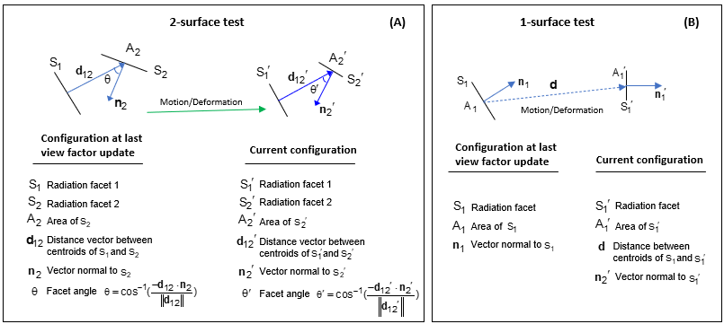
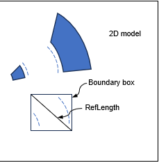
RefLength in the denominator of the 1-surface facet spacing threshold test is a length scale representative of the radiation facet spacing for an enclosure. It is automatically calculated by putting a bounding box on the radiation facets and computing the diagonal of the bounding box. RefLength is dynamic and updates when view factors are updated. See the following figure for a depiction of how RefLength is computed.
For details on how the kinematic-based thresholds are tested to determine if view factors are updated, see Kinematic-based algorithm in the notes.
Command Default
Although the command is not required for solution, if you do not issue VFUP, view factors are not updated at the substep level. Consequently, results of thermal radiation modeling may be inaccurate because they do not account for changes in the view factors of radiation surfaces as they deform or move.
Notes
Deformation and/or motion of radiating surfaces during an anlysis can cause inaccuracies in radiation calculations if the view factors are not updated to account for these changes. Issue VFUP,DEFINE,ON to enable view factor updates at the substep level and improve simulation accuracy for an analysis that includes all of the following conditions:
Updates occur only if all of these conditions are met:
When view factor updating is enabled (VFUP,,ON), radiation facet areas are recalculated along with the view factors according to the specified criteria. To specify the updating criteria, you must re-issue the VFUP command and choose one of the following:
frequency-based criteria (
Opt= FRQU) to have updates occur at defined substep (OPT2) and pass (OPT3) frequencies, regardless of geometric changes to radiation facets,or
kinematic-based criteria (
Opt= KNEX, KNIM, or KNI1) to have updates occur only if relative changes in facet spacing, areas, or angles exceed thresholds defined byOPT2,OPT3, andOPT4, respectively.
Controlling the frequency of view factor updates
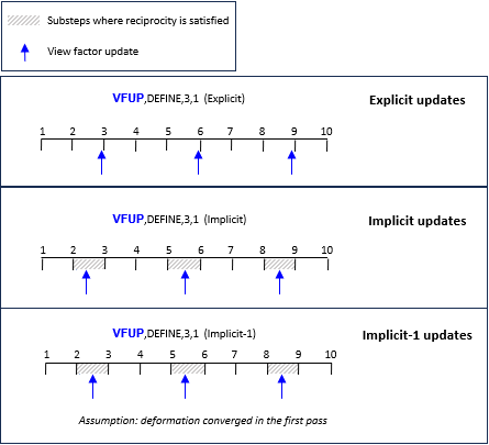
The full solution method (THOPT,FULL) with radiosity has three nested loops, which occur for each load step: the substep (or time step) loop, the multipass loop, and the Newton-Raphson (NR) loop. Displacements and temperatures, in addition to any other DOFs that may be included in your coupled-field analysis, are computed in the NR loop. The view factors / radiation areas can be recalculated at different points during the solution, as depicted in Figure 33: View Factor Update Timing. There are three timing strategies, Explicit, Implicit, and Implicit-1, and the implications of each timing strategy are detailed in the following discussion.
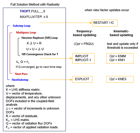
As seen in the figure, implicit updates occur within the multipass loop, and updated
view factors are used in the current substep. Instead, explicit updates occur at the end of
the time step, and updated view factors are used in the next time step. An additional update
occurs before entering the substep loop for a restart (ANTYPE,, RESTART) or
if you have imposed initial conditions on the displacements (IC) as
indicated.
There is a trade-off between accuracy and computational cost as updating the view factors at the substep level improves accuracy but also increases the solution time. To control the timing of view factor updates and whether updates are based on geometric changes to the radiation facets due to kinematic motion or deformation during solution, you must choose one of these options:
Opt= FRQU: Specify the substep (OPT2) and pass (OPT3) frequency at which view factor updates occur. Updates happen at the specified frequency, regardless of whether deformation or motion causes significant changes to the radiation facets.Opt= KNEX, KNIM, or KNI1: The view factors are updated only if changes in the radiation facets due to motion/deformation exceed a specified threshold (OPT2,OPT3, orOPT4). As shown in Figure 33: View Factor Update Timing and described in detail below, the difference between these kinematic-based update options is when the testing and updates occur.
There are three timing strategies:
Explicit - View factors are updated at the end of a substep after a converged coupled-field solution is achieved, and the updated view factors are used in the next time step.
For
Opt= FRQU — You chose the explicit strategy by settingOPT3= 0, and the value specified for the substep frequency,OPT2, determines which substeps include view factor updating. By default,OPT2= 1, and view factors are updated at the end of every substep.For example, if you issue: View factors are updated VFUP,DEFINE,FRQU,3,0 at the end of substeps 3,6,9,... For
Opt= KNEX — At the end of every substep, the facets are tested (see Kinematic-based algorithm for details) and view factors updated only if one of the three kinematic-based thresholds (OPT2,OPT3,OPT4) are exceeded.For example, if you issue: Radiation facets are tested and view factors are updated VFUP,DEFINE,KNEX at the end of every substep. Updates occur only if one of three kinematic-based thresholds (facet spacing, area, or angle) exceeds the default value of 0.05 VFUP,DEFINE,KNEX,0.1,,0 at the end of every substep. Updates occur only if the relative change in facet spacing threshold exceeds 0.1 or the relative change in facet area exceeds the default value of 0.05. Explicit is the most stable timing strategy. If you have convergence difficulties, explicit updates are recommended. For an accurate solution, the substep size must be small. Explicit updates may lead to an energy imbalance in the radiosity solution since the view factor facet areas were calculated in the preceding time step. For further details, see the discussion related to Figure 37: View Factor Updates and Reciprocity.
Implicit - View factors are updated within the radiation multipass loop, after the Newton-Raphson (RP) loop has produced a converged coupled-field solution, and are used in the current pass and substep.
For
Opt= FRQU — The value of the pass frequency,OPT3, determines which passes will update the view factors. To have implicit view factor updating, you must setOPT3to something other than its default value of zero.For example, if you issue: View factors are updated VFUP,DEFINE,FRQU,5,3 in passes 3,6,9,... for substeps 5,10,15... For
Opt= KNIM — The testing and view factor updating if a kinematic-based threshold is exceeded (see Kinematic-based algorithm for details) occurs within the radiation multipass loop, after the Newton-Raphson (RP) loop has produced a converged coupled-field solution. Updated view factors are used in the current pass and substep.For example, if you issue: Radiation facets are tested and view factors are updated VFUP,DEFINE,KNIM in every pass for every substep. Updates occur only if one of three kinematic-based thresholds (facet spacing, area, or angle) exceeds the default value of 0.05 VFUP,DEFINE,KNIM,0.1,0,0.1 in every pass for every substep. Updates occur only if the relative change in the facet spacing or angle threshold exceeds 0.1. Implicit updates are useful when you have strong nonlinearities, strong structural-thermal coupling, or rapid changes in surface geometry. However, implicit updates can be computationally expensive as view factors are recalculated multiple times within a single substep. Also, Implicit updates of view factors can lead to instabilities and convergence difficulties.
Implicit-1 - View factor updating occurs onlly in the first pass of the radiation multipass loop.
For
Opt= FRQU — View factors are updated in the substeps prescribed by the value of the substep frequency,OPT2, but they are updated only in the first pass of the radiation multipass loop. To have implicit-1 view factor updating, specify -1 forOPT3.For example, if you issue: View factors are updated VFUP, DEFINE, FRQU, 5, -1 only in pass 1 for substeps 5,10,15... For
Opt= KNI1 — The facet testing and view-factor updating if a kinematic-based threshold is exceeded (see Kinematic-based algorithm for details) occurs only within the first pass of the radiation multipass loop, after the Newton-Raphson (RP) loop has produced a converged coupled-field solution.For example, if you issue: Radiation facets are tested and view factors are updated VFUP,DEFINE,KNI1 in the first pass for every substep. Updates occur only if one of three kinematic-based thresholds (facet spacing, area, or angle) exceeds the default value of 0.05 VFUP,DEFINE,KNI1,0.1,0,0 in the first pass for every substep. Updates occur only if the relative change in the facet spacing threshold exceeds 0.1. Use this timing strategy when the motion of bodies in your model is completely specified, as in rigid body motion (translation and rotation). It is most efficient and accurate to update the view factors in the first pass only when the NR loop achieves a converged structural solution in the first pass and the structural solution does not change for subsequent passes.
Kinematic-based algorithm
For Opt = KNEX, KNIM, or KNI1, the
kinematic-based criteria are used in the algorithm depicted below to test and update view factors.
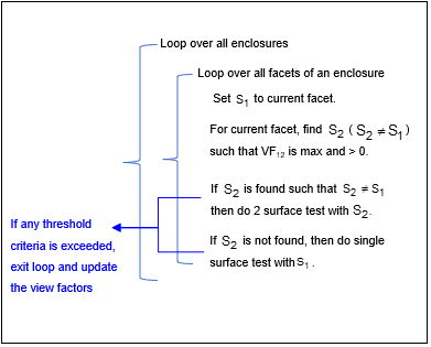
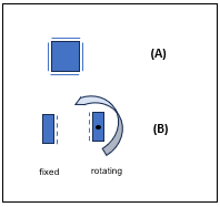
In most practical situations, S2 will be found and the 2-surface test will be done. In some situations, when the facet only radiates to the environment, the 1-surface test is required. Two examples of when a 1-surface test is encountered are shown in the following figure. For a 2D square with four radiating surfaces around it, the 4x4 view factor matrix is zero, and only single surface tests will be done as the body translates (A in the figure). The second example (B) is two radiating surfaces, one fixed and one rotating. When the rotating surface reaches an 180 degree rotation, the view factor matrix becomes zero, and the 1-surface test will be encountered.
Notes on kinematic-based and frequency-based updates
Kinematic-based updates (Opt = KNEX, KNIM,
or KNI1) are sensitive to motion while frequency-based updates (Opt
= FRQU) are not. For example, consider a 2 plate problem with total loadstep time = 100. Plate
1 is fixed and plate to moves only from time 10-20. Frequency-based updates will occur from
time = 0 - 100, but kinematic-based updates will occur from time 10-20.
If an enclosure is undergoing rigid-body translation or rotation, and there is no change to the radiation facets:
If you are using kinematic-based updates, view factors will not be updated if the 2-surface test is encountered. However, if a 1-surface surface is encountered, they will be updated.
If you are using frequency-based updates, view factors are updated at the prescribed frequency regardless of whether or not the radiation facets are moving.
When you have no knowledge about body deformation prior to the simulation, kinematic-based updates are a good option since view factor updates will only be triggered if the geometry of the radiation surfaces move or deform significantly.
For kinematic-based updating, when bodies are moving away from each other, updates occur less often. Vice-versa, when bodies move toward each other, updates occur more frequently.
Restrictions / limitations
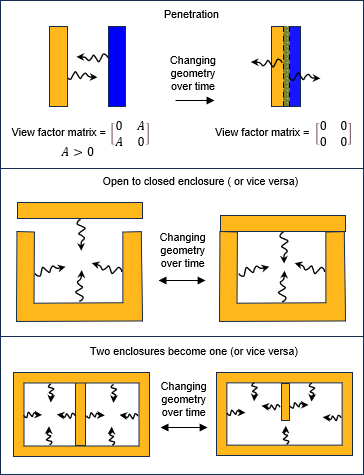
Enclosure status change and penetration must be avoided — Simulations using the VFUP to update view factors at the substep level are invalid if an enclosure status changes or the surface of a radiating body penetrates the surface of another radiating body. Figure 36: Examples of Radiation Problems that Undergo an Enclosure Status Change illustrates some examples of enclosure status changes that must be avoided. For example, if two radiating bodies in close proximity penetrate each other due to thermal expansion during the analysis, their view factors become zero, and results using the VFUP command to update view factors are unpredictable and inaccurate. It is better to model bodies within close proximity using thermal contact radiation (contact and target elements: CONTA172, CONTA174, CONTA175, CONTA178,TARGE169, and TARGE170).
You must also be careful to avoid an enclosure status change, for example if movement or deformation in the analysis causes an open enclosure to become closed or vice versa. If an enclosure is undergoing a status change in your analysis, split the load step into multiple load steps such that:
There is no status change in the individual load steps.
VFSM settings are appropriate for the enclosure status in individual load steps.
View factor Updates and Reciprocity — For explicit updates, view factors are recalculated at the end of the substep and
applied in the next substep. Consequently, they violate the reciprocity rule in the next
substep as the radiating areas change since the view factors were calculated from the areas
of the previous substep. This may lead to energy imbalance issues. The same problem exists
if you specify a substep (OPT2) or pass
(OPT3) frequency other than one. Figure 37: View Factor Updates and Reciprocity
illustrates this issue for different updating strategies. Reciprocity / row sum properties
are only satisfied in substeps where view factors are updated in every pass
(OPT3 = 1) provided you have used the VFSM
command appropriately (see View Factors in the Theory Reference).
Supported/restricted commands at the substep level with VFUP,DEFINE,ON
The following commands are not supported at the substep level:
The following commands may be used to query and print view factors or average view factors at the substep level:
The following radiation commands are valid at the substep level, and may be used with view factor updating enabled (VFUP,DEFINE,ON):
Settings on the VFSM command to adjust view factors (view factor smoothing) for different enclosures are valid for all substeps. However, if there is an enclosure status change during a load step, VFSM settings may become inappropriate and results inaccurate. See earlier discussion on inaccurate results if motion or deformation causes an enclosure status change (Figure 36: Examples of Radiation Problems that Undergo an Enclosure Status Change). To model a situation where deformation changes the enclosure status, you must solve the problem in multiple load steps and change VFSM settings in each load step to accurately model the state of the enclosure.