The geometry of the model consists of three bodies: the block, the top roller, and the side roller which are created in Design Modeler. The block is a solid body, and the rollers are of surface bodies with 0.01 m thickness. The following figure shows the dimensions of all three bodies.
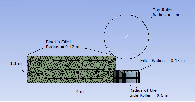
Notice that the block has small fillets at either end of the top face. The fillets help to establish contact with the top roller. Without them, the sharp corner of the block would cause local singularities, and the analysis would diverge.
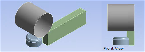
Leveraging the symmetry of the structure, only one-quarter of the model is included in the simulation. A bilinear isotropic hardening material model is used for the block body. The top roller and side roller are modeled as rigid bodies.
Modeling for this problem involves the following tasks:
The following figure shows the geometry used in the simulation, which is one-quarter of the full model. Two Symmetry Regions are defined to simulate the one-quarter model geometry.
The first symmetry region is scoped to the side face of the block, selecting the Global X-axis as the symmetry normal.
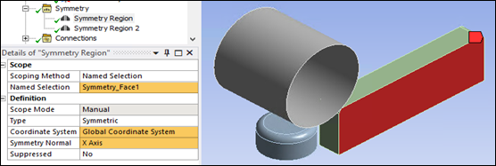
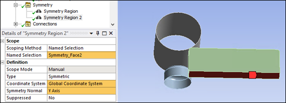
The second symmetry region is scoped to bottom face of the block, selecting the Global Y-axis as the symmetry normal.
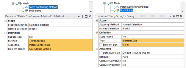
The Stiffness Behavior of the block is set to Flexible. The Tetrahedrons Patch Conforming Method is used to mesh the block with SOLID187 elements. The default setting of program controlled for the global Element Order results in quadratic elements for this model. Body Sizing of 0.1 m is used for the Block body as shown in the following figure.
MASS21 elements are used to model the rollers since their Stiffness Behavior is defined as Rigid.
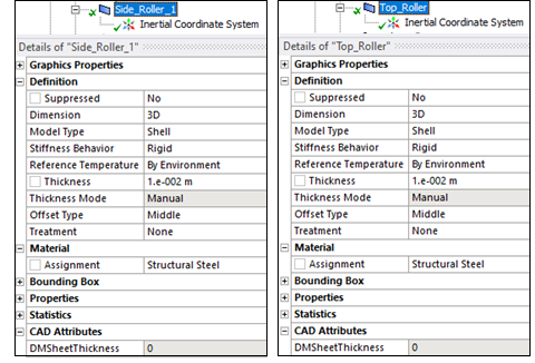
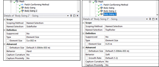
Body Sizing controls are used for contact target elements. Body Sizing of 0.05 m for side roller and of 0.25 m for top roller are used as shown in the following figure.
Two contact pairs are defined to simulate contact occurring between block and rollers during the block movement:
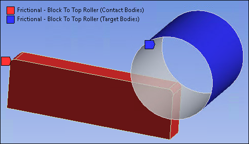
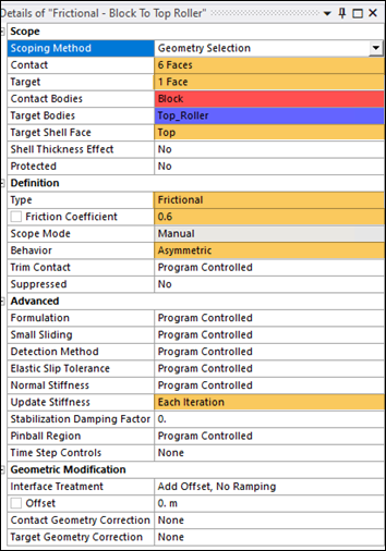
Frictional contact with a friction coefficient of 0.6 is defined between the rigid top roller face and 6 faces (all faces excluding faces used to define symmetry regions) of the block to be in contact. The following contact settings are used as highlighted in the figures below:
Select Top face as Target Shell Face.
Contact Behavior is Asymmetric.
Set Update Stiffness to Each Iteration.
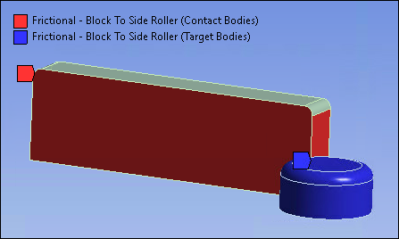
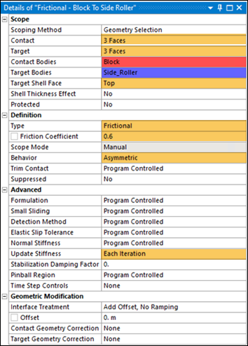
Frictional contact with a friction coefficient of 0.6 is defined between the rigid side roller faces and 3 faces (front, back and side) of the block to model their contact.
The following contact settings are used as highlighted in the following figures:
Select Top face as Target Shell Face
Set contact Behavior to Asymmetric.
Set Update Stiffness to Each Iteration.