The line bodies model type is set to Thermal Fluid and the fluid discretization method is set to Upwind/Linear. A fluid cross sectional area of 31.1709 mm2, 7.5473 mm2, and 3.0789 mm2 is used for the line bodies with cross sectional radii of 3.15 mm, 1.55 mm ,and 0.99 mm respectively.
3D FLUID116 element is used to model 10 fluid bodies which can conduct heat and transmit fluid between its two primary nodes. See the element description for FLUID116 for further details.
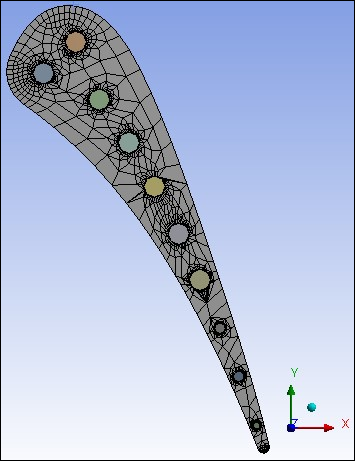
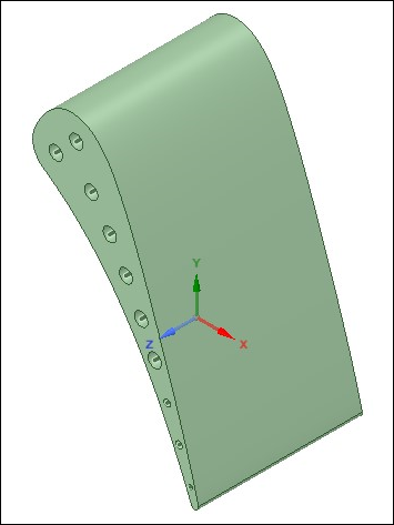
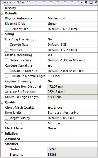
The solid region is meshed with SOLID278 elements. Lower order elements are used. The model and mesh settings used are reported in the figures below.
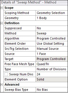
The settings used for the sweep mesh method for the solid mesh are shown in the figure below.
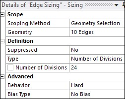
Edge Sizing with 24 divisions and hard behavior is used to mesh fluid bodies.