


The following topics describe the modeling decisions and setup used:
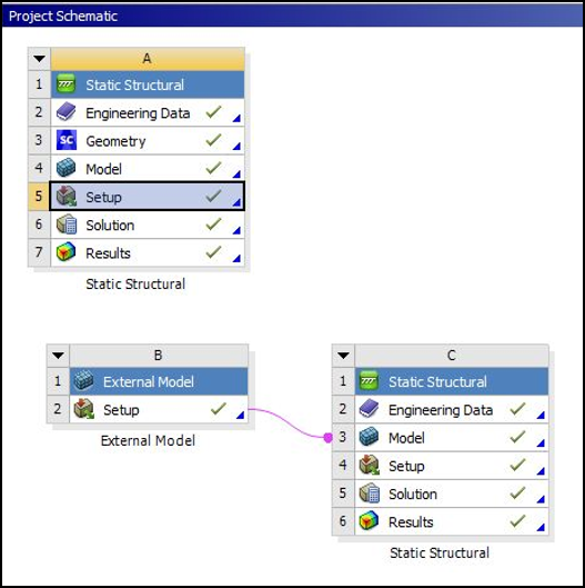
Figure 16.5: Project Schematic shows the setup in Workbench. The rectangular block is modeled using a 3-D Static Structural system (A in the figure) with default Structural Steel material. The default material properties of stainless steel are listed in Material Properties. The rectangular block geometry is provided in two equivalent input files: one created in SpaceClaim (Rect_Block_TD_WB_016.scdoc) that is supported on Windows only, and one created in DesignModeler (Rect_Block_TD_WB_016.agdb) that is supported on both Windows and Linux. The geometry is attached as described in Attach Geometry/Mesh in the Mechanical User's Guide.
The X-Joint Pipe is modeled using an External Model system to import the mesh file (xjoint_pipe_with_warped_flaw.cdb, which is included in the downloadable input files). The setup cell of the External Model system is linked to the model cell of another Static Structural system with default Structural Steel material to setup the X-Joint Pipe analysis (B and C in Figure 16.5: Project Schematic).
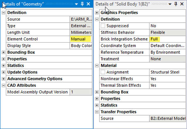
The rest of the modeling specifications are made in the Mechanical Application. For the X-Joint Pipe model, the Element Control property of Geometry is set to Manual to enable the Full Brick Integration Scheme for the solid body elements (SOLID186) as shown in the Details windows below.
The analysis makes use of Named Selection objects to define the crack and boundary conditions in both the rectangular block and the X-Joint Pipe models. Local coordinate systems are also used in both models to define the crack coordinate system.
Rectangular Block Model
The figure below shows the scoping and settings of the Semi-Elliptical Crack object used for crack modeling in the rectangular block model.
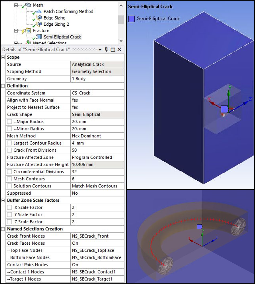
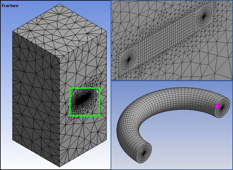
The Semi-Elliptical Crack object generates the recommended SOLID186 elements around the crack front as shown in the figure below. If any component in the global coordinate system is not orthogonal to the crack surface, create a local coordinate system with one component normal to the crack surface. This action is necessary to define the crack coordinate system (crack plane normal).
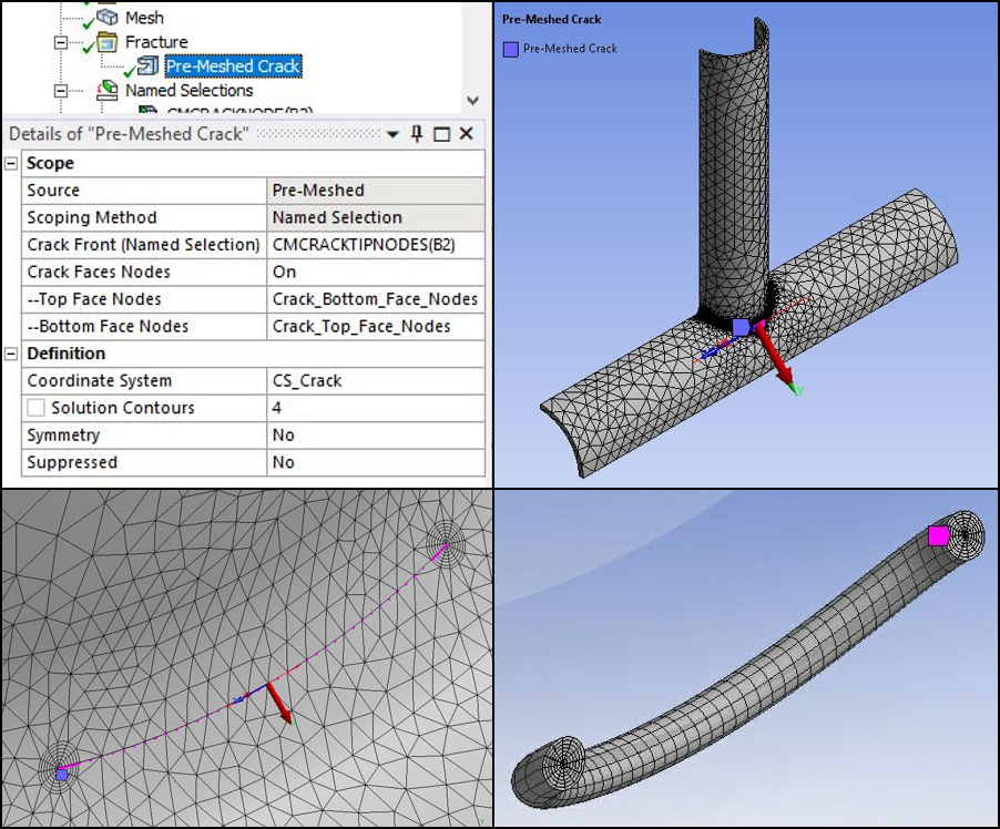
X-Joint Pipe Model
A Pre-Meshed Crack object with body scoping and the settings shown below is used for Crack modeling in X-Joint Pipe model. This approach uses the external mesh, which contains a compatible crack mesh (crack front, top-bottom faces, and SOLID186 elements around the crack front).
Fracture parameter computation commands (CINT) are sent to the solver according to the settings of the Semi-Elliptical and Pre-Meshed Crack objects and Fracture Controls specified in Analysis Settings.