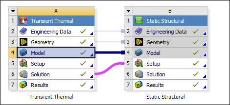
To explore this example problem, you can download the input files, which include the DesignModeler .agdb file. The geometry is attached as described in DesignModeler (*.agdb) in the CAD Integration. Insert the Thermal-Structural linked analysis systems as shown in the Workbench flowchart below.
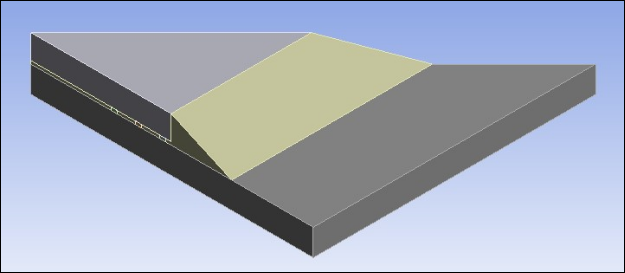
The geometry is made up of bodies that model the solder, underfill, chip and substrate.