The following results topics for the FSW simulation are available:
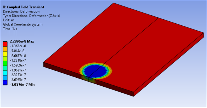
It is important to observe the change in various quantities around the weld line during the FSW process. The following figure shows the deflection of the workpiece due to plunging of the tool in the first load step.
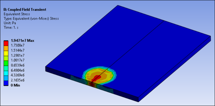
The deflection causes high stresses to develop on the workpiece beneath the tool, as seen below.
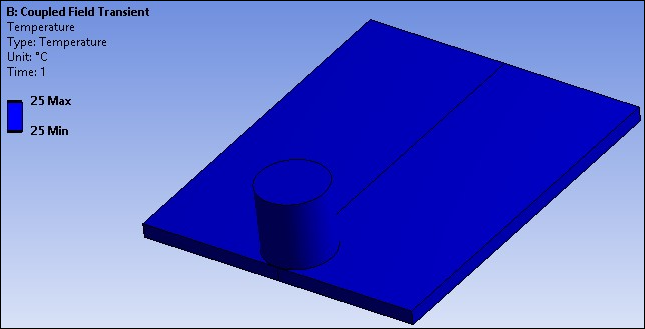
Following load step 1, the temperature remains unchanged (25 °C), as shown in the following figure.
As the tool begins to rotate at this location, the frictional stresses develop and increase rapidly. The following two figures show the increment in contact frictional stresses from load step 1 to load step 2:
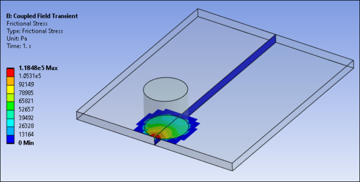
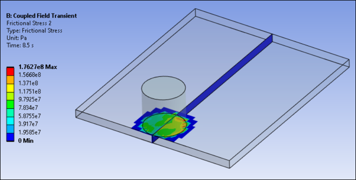
All frictional dissipated energy is converted into heat during load step 2. The heat is generated at the tool-workpiece interface. Most of the heat is transferred to the workpiece (FWGT is specified to 0.95). As a result, the temperature of the workpiece increases rapidly compared to that of the tool.
The following two figures shows the temperature rise due to heat generation in the second and third load steps:
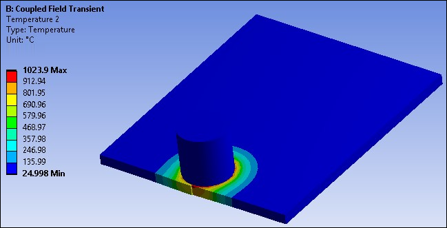
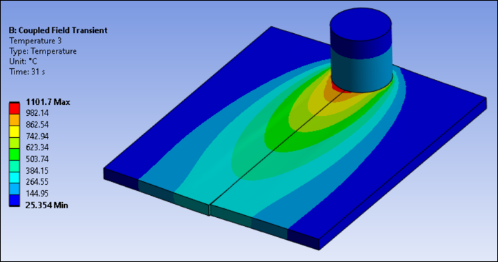
The maximum temperature on the workpiece occurs beneath the tool during the last two load steps. Heat generation is due to the mechanical loads. No external heat sources are used. As the temperature increases, the material softens and the coefficient of friction decreases. A temperature-dependent coefficient of friction (0.4 to 0.2) helps to prevent the maximum temperature from exceeding the material melting point.
The observed temperature rise in the model shows that heat generation during the second and third load steps is due to friction between the tool shoulder and workpiece, as well as plastic deformation of the workpiece material.
The melting temperature of 304L stainless steel is 1450 °C. As shown in the following figure, the maximum temperature range at the weld line region on the workpiece beneath the tool is well below the melting temperature of the workpiece material during the second and third load steps, but above 70 percent of the melting temperature:
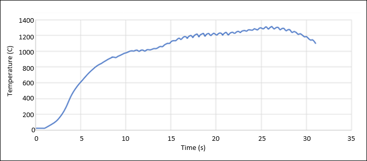
The two plates can be welded together within this temperature range.
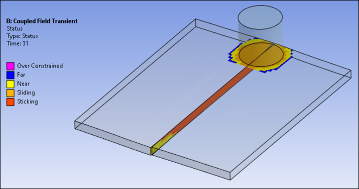
A bonding temperature of 900 °C is already defined for the welding simulation at the interface of the plates. The contact status at this interface after the last load step is shown in the following figure: