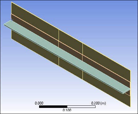
To create solid shell composite bodies, two different ACP systems are used. Shell bodies are first created in Ansys DesignModeler, then imported into Mechanical to generate the required named selections and mesh. Layers, stackups, oriented element sets, modelling plies, and solid composites are defined within ACP. They are then imported into Mechanical.
Due to the symmetry of the problem, it is possible to model only one representative section of the whole panel. The representative section shown below contains a 600 mm x 160 mm portion of the panel skin and one stiffener assembly.
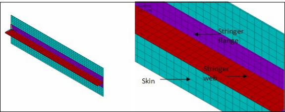
The section is meshed with SOLSH190 elements, as shown below. Note that the elements on the skin and the flange do not need to match when the interfaces are modeled with contact elements.
A secure bond is assumed between the web and the flange. This perfect bonding is simulated using common nodes for both components.
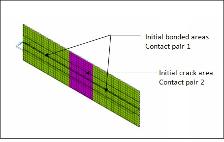
The interfaces between the skin and the flange are meshed with CONTA174 and TARGE170 elements. Two distinct contact pairs are established, as shown in Figure 5.5: Two Contact Pair Definitions (Initial Crack and CZM Area). Since debonding is permitted in the entire interfacing area between the skin and flange, KEYOPT(12) = 6 is set for the CONTA174 elements to allow only an initially bonded contact, and a cohesive zone material (CZM) is assigned to these elements for modeling any subsequent debonding. An area of artificial imperfection is introduced in the skin-flange interface. In this area, the bonding material is completely missing and the standard contact behavior (KEYOPT(12) = 0) is assigned to the CONTA174 elements.


