The following modeling topics are available:
Brake-squeal problems typically require manual calculations of the unsymmetric terms arising from sources such as frictional sliding, and then inputting the unsymmetric terms using special elements (such as MATRIX27). It is a tedious process requiring a matched mesh at the disc-pad interface along with assumptions related to the amount of area in contact and sliding.
3-D contact elements (CONTA17x) offer a more efficient alternative by modeling surface-to-surface contact at the pad-disc interface. With contact surface-to-surface contact elements, a matched mesh is unnecessary at the contact-target surface, and there is no need to calculate the unsymmetric terms.
Contact surface-to-surface elements offer many controls for defining contact pairs, such as the type of contact surface, algorithm, contact stiffness, and gap/initial penetration effect.
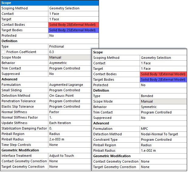
Frictional surface-to-surface contact pairs with a 0.3 coefficient of friction are used to define contact between the brake pads and disc to simulate frictional sliding contact occurring at the pad-disc interface. Bonded surface-to-surface contact pairs are used to define the contact for other components which will be always in contact throughout the braking operation.
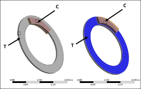
The bonded contact definition is provided between faces of following part pairs/combinations. The contact and target bodies are indicated in Figure 1.2: Contact Target Pairs for Bonded Contact as C and T, respectively. This illustration is a guide. Contacts are not defined between bodies, but between faces corresponding to those bodies.
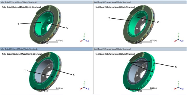
Similarly, the contact and target pairs for the frictional contact are shown below.
The augmented Lagrange algorithm is used for the frictional contact pairs, as the pressure and frictional stresses are augmented during equilibrium iterations in such a way that the penetration is reduced gradually. The augmented Lagrange algorithm also requires fewer computational resources than the standard Lagrange multiplier algorithm, which normally requires additional iterations to ensure that the contact compatibility is satisfied exactly. The augmented Lagrange is well suited for modeling general frictional contact, such as the contact between the brake pad and disc defined in this example.
An internal multipoint constraint (MPC) contact algorithm is used for bonded contact because it ties contact and target surface together efficiently for solid-solid assembly. The MPC algorithm builds equations internally based on the contact kinematics and does not require the degrees of freedom of the contact surface nodes, reducing the wave front size of the equation solver. A contact detection point is made on the Gauss point for frictional contact pairs, and on the nodal point (normal-to-target surface) for MPC bonded contact pairs.
The CMROTATE command defines constant rotational velocities on the contact/target nodes to generate internal sliding motion. The specified rotational velocity is used only to determine the sliding direction and has no effect on the final solution. The element component used should include only the contact or the target elements that are on the brake disc/rotor. In this example, the target elements are defined on the disc surface and the contact elements are defined on the pad surface. The target elements attached to the disc surface are grouped to form a component named E_ROTOR which is then later specified on the CMROTATE command to generate a sliding frictional force.
The CMROTATE command must be inserted as a command snippet as there are no native features that currently support this command in Workbench. For the full non-linear perturbed modal analysis method, it is inserted under the Static Structural Analysis, and for the linear non-prestressed modal analysis method, under the Modal Analysis.
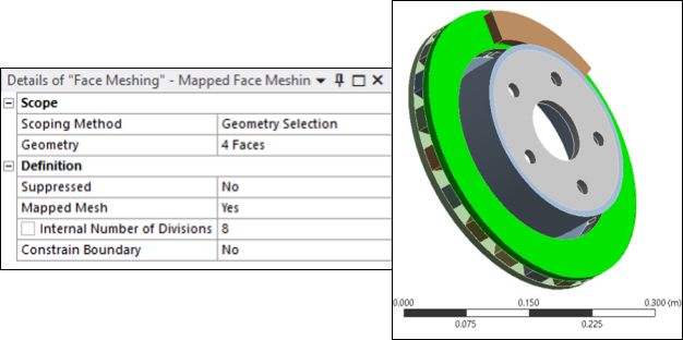
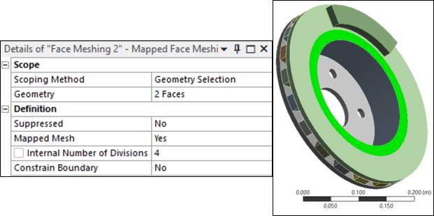
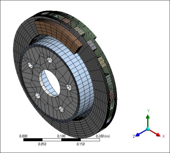
Brake discs, pads and all other associated components are meshed with 20-node structural solid SOLID186 elements with uniform reduced-integration element technology. The face mesh and edge sizing tools are used to obtain a refined mesh at the pad-disc interface and improve solution accuracy. For problems with a large unsymmetric coefficient, a finer mesh should be used at the pad-disc interface to accurately predict the unstable modes. The brake disc-pad assembly is meshed with a total of 60351 nodes and 11473 elements. Mapped face meshing is used to control the mesh on the disc-pad faces. Number of divisions for edge sizing are kept at 8 for the pads and the bodies between the discs.