Leveraging the symmetry of the structure, only half of the rubber boot is modeled. For the rubber boot, the hyperelastic material model is used. The shaft is considered as a rigid body.
Modeling for this problem involves the following tasks:
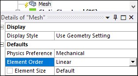
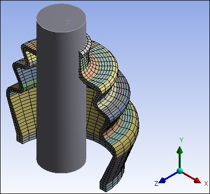
Lower order hexahedron elements (SOLID185) are used to mesh the rubber boot as shown in the figure below. This model has 3387 elements.
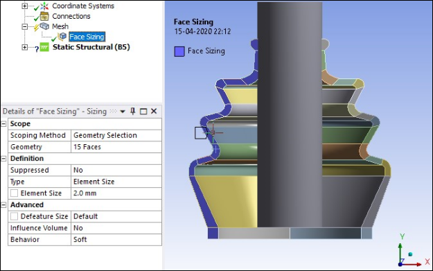
Face Sizing of 2 mm is used for 15 faces of the rubber boot as shown in the following figure.
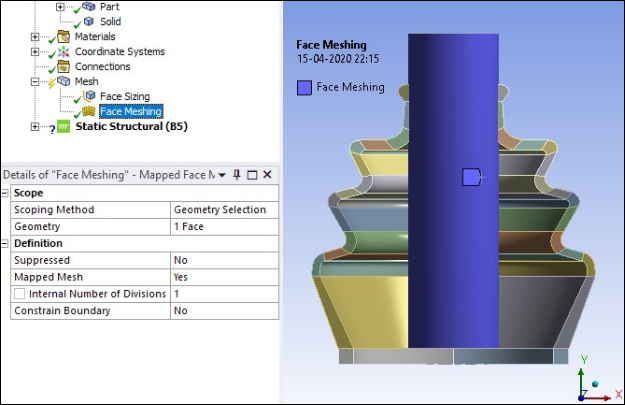
Mapped face meshing is used for the rigid shaft as shown in the following figure.
The final meshed model is shown in the figure below. It has total 2641 elements.
Three contact pairs are defined to simulate contact occurring in the rubber boot during the shaft movement:
Rigid flexible contact between the rigid cylindrical shaft and the inner surface of the rubber boot.
Self contact at the inner surface of the rubber boot using the surface-projection-based contact method.
Self contact at the outer surface of the rubber boot using the surface-projection-based contact method.
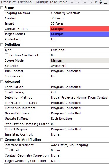
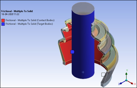
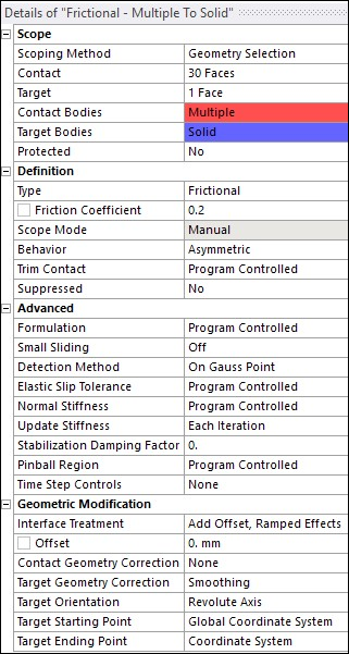
Frictional contact with a friction coefficient of 0.2 is defined between rigid shaft face and inner 30 faces of the rubber boot to be in contact.
The following contact settings are used.
Include interference with ramped effects (KEYOPT(9) = 2).
Set the location of the contact detection point at the gauss integration point (KEYOPT(4) = 0).
Update contact stiffness at each iteration (KEYOPT(10) = 2).
The following figure shows details of contact settings. The location of coordinate system used for target ending point is at the top face of shaft and has same orientation as global coordinate system.
Two frictional self-contacts with a friction coefficient 0.2 are defined between the 30 inner and outer faces of rubber boot to be in self-contact.
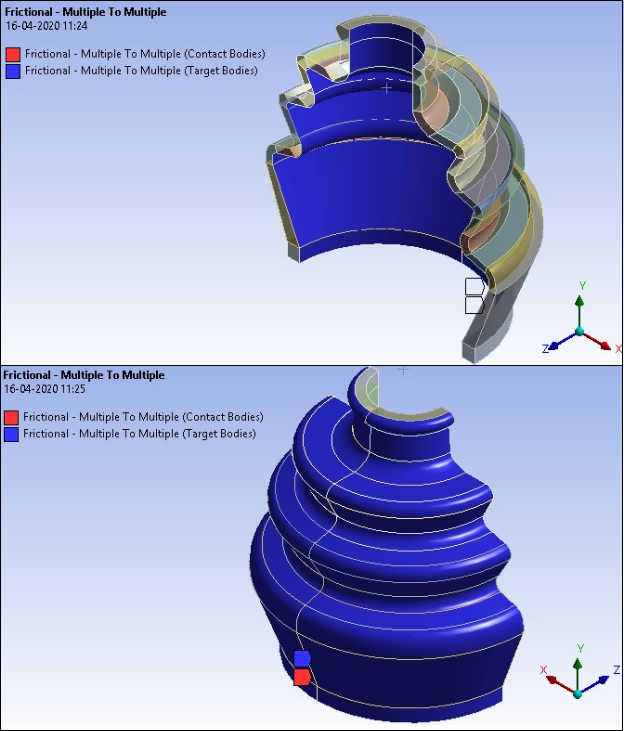
To model a self contacting pair, both the target and contact surfaces are the same.
The following contact settings are used:
Surface-projection-based contact detection method (KEYOPT(4) = 3)
Update contact stiffness at each iteration (KEYOPT(10) = 2)