


VM-WB-MECH-106
VM-WB-MECH-106
Motion of a Pendulum Under Gravity Load
Overview
|
Reference: |
Da Silva, Marcelo R.M. Crespo. (2016). Fundamentals of Dynamics and Analysis of Motion. (1st ed., Vol 1). Mineola, NY: Dover Publications. 129-136. |
|
Solver(s): |
Ansys Mechanical with Variable Load Extension |
|
Analysis Type(s): |
Rigid Body Dynamics with Variable Load Extension |
|
Analysis Components |
Point Mass |
Test Case
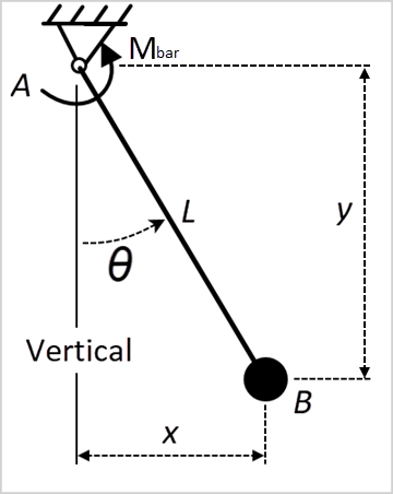
Consider a pendulum consisting of a point mass B attached to the free end of a pinned bar L. The system moves in a vertical plane, and the only forces acting on the mass are the gravitational attraction of the earth and the force applied to the bar. A sensor placed in the system measures the angle θ and generates a signal. The signal serves as an input to the motor at A so that Mbar = -K θ(t), where K = 4 Nm/rad. Determine the minimum and maximum relative rotation of the bar.
| Material Properties | Geometric Properties | Loading |
|---|---|---|
| Point Mass = 0.2 kg |
L = 60cm θ (0) = 0 |
Gravitation = 9.81 m/s2 Mbar = -K θ(t)
K = 4 Nm/rad |

Analysis Assumptions and Modeling Notes
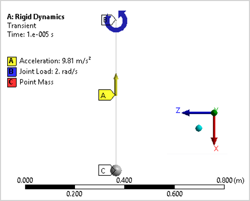
Refer to Figure 145: Workbench Model below. The pendulum has a frictionless pinned end B and a point mass C on the free end. The bar is assumed to be massless so the density is set to 1e-10 kg which is insignificant compared to the point mass of 0.2 kg. The stiffness behavior is set to rigid. Rotational movement is assumed to be in the vertical plane about the Y Axis, so a revolute joint restricts the movement to the XZ plane.
The initial angular velocity of the bar is 2 rad/s. A gravity load of -9.81 m/s2 is applied to the model. A moment of -K θ(t) is applied to the bar.
For Analysis Settings, the number of steps is set to two, and the end-time step is set to two seconds. The first time-step is 1e-5 seconds. This step will be used to set the initial angular velocity condition.
A Joint Load is applied to the Revolute - Ground to Massless Bar. The Type is set to Rotational Velocity. The initial step condition is set to 2 rad/s. The load is deactivated for the rest of the simulation.
For Solution Settings, a Joint Probe is scoped to the boundary condition Revolute - Ground to Massless Bar. The relative rotation result is selected in the Z axis.
To define the variable moment, the VariableLoad extension will be used: A Rigid Dynamics Measures folder is inserted. In Joint Measures, the revolute joint rotation is captured. In Derived Measures, rotation in Z is selected. Measure Varying Joint Load is added to the revolute joint in the ROTZ degree of freedom. Joint Angle Z derived measure is selected for the input. The variable moment equals 4 when the rotation is -1 and equals -4 when the rotation is 1.
Results Comparison
The expected maximum relative rotation value (with a null applied moment) according to the formulation is 13.5 degrees. The minimum relative rotation is -13.5 degrees.
| Result | Target | Mechanical | Error (%) |
|---|---|---|---|
| Maximum Relative Rotation of the Massless Bar | 13.5 | 13.51 | 0.096 |
| Minimum Relative Rotation of the Massless Bar | -13.5 | -13.52 | 0.151 |