VM-EXD-MECH-009
VM-EXD-MECH-009
Coriolis Component of Acceleration (Rotary Engine Problem)
Overview
| Reference: | Any Basic Kinematics Book |
| Analysis Type(s): | Explicit Dynamics 3D (Fully Rigid) |
| Elements: | Rigid Body Elements |
| Boundary Conditions: | Fixed Constraint, Joint Load (Rotational Velocity) |
| Structural Interactions: | No |
| Fluid-Structure Interactions: | No |
| Connections: | Cylindrical and Translational |
| Materials: | Steel |
Test Case
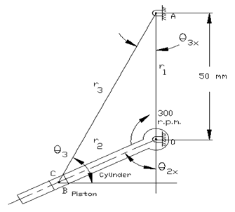
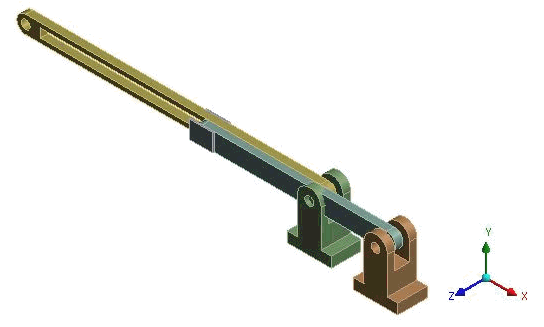
Following is a kinematics diagram of one cylinder of a rotary engine:
OA is 50 mm long and fixed at point o.
The length of the connecting rod AB is 125 mm.
The line of stroke OB is inclined at 50 degrees to the vertical.
The cylinders are rotating at a uniform speed of 300 rpm in a clockwise direction, about the fixed center O.
The analysis determines the angular acceleration of the connecting rod.
| Material Properties | Geometric Properties | Loading |
|---|---|---|
|
E = 2E11 Pa ν = 0.3 |
Connecting rod AB is 125 mm Crank OA is 50mm long OB is inclined at 50 degrees to the vertical. |
Constant rotational velocity = 300 rpm |
Analysis

Angular acceleration of the connecting rod (shown in Figure 246: Rotary Engine Cylinder Schematic) is given by:
Result Comparison
| Result | Target | Explicit Dynamics [1] | Error (%) |
|---|---|---|---|
| Angular acceleration (radian/s2) | 294.52 | 294.36 | -0.054 |
To compare this result to that obtained using rigid body dynamics, see VM-WB-MECH-056.


