VM-EXD-MECH-008
VM-EXD-MECH-008
Projector Mechanism -- Finding the Acceleration of a Point
Overview
| Reference: | Any Basic Kinematics Book |
| Analysis Type(s): | Explicit Dynamics 3-D (Fully Rigid) |
| Elements: | Rigid Body Elements |
| Boundary Conditions: | Fixed Constraint, Joint Load (Rotational Velocity) |
| Structural Interactions: | No |
| Fluid-Structure Interactions: | No |
| Connections: | Revolute Joint |
| Materials: | Steel |
Test Case
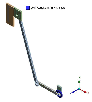
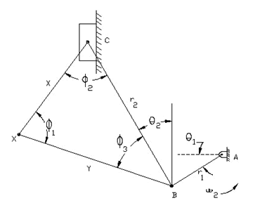
The mechanism shown is used to pull a movie through a projector:
The mechanism is driven by the drive wheel rotating at a constant -58.643 rad/s. All link lengths are constant:
Link AB length r1 = 18mm
Link BC length r2 = 48mm
Length BX = x = 45 mm and CX = y = 28 mm
The horizontal distance between A and C is length = 34 mm.
The analysis determines the acceleration of point C with a change of angle of link AB (θ 1) from 0 to 60 degrees in a counter-clockwise direction.
| Material Properties | Geometric Properties | Loading | |||||||
|---|---|---|---|---|---|---|---|---|---|
|
|
|
Results Comparison
| Results | Target | Explicit Dynamics [1] | Error (%) |
|---|---|---|---|
| Relative acceleration (θ 1 = 10) mm/s2 | -12.06 | -12.128 | 0.564 |
| Relative acceleration (θ 1 = 30) mm/s2 | 1.317 | 1.3155 | -0.114 |
| Relative acceleration (θ 1 = 60) mm/s2 | 6.739 | 6.7601 | 0.313 |
To compare these results to those obtained using rigid body dynamics, see VM-WB-MECH-055.


