


Mechanical enables you to import load data, thickness data, or element orientation coordinate data from external source files directly into the application. Go to a section topic:
Import Options
- Imported Loads
The Imported Loads menu of the Environment object context ribbon includes an option to import load data. This option opens the External Data dialog.
- Imported Thickness and Element Orientations
The Imported Thickness and Imported Element Orientations options of the Geometry object context ribbon enable you to import element orientation data or shell thickness data from an external file. Both of these options open the External Data dialog.
External Data Dialogs
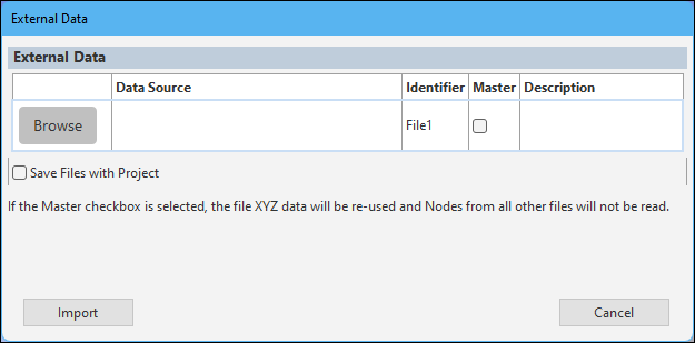
From the appropriate object, select the desired option. The application automatically inserts the corresponding object into the tree and displays the External Data dialog. Use this dialog to specify the desired file(s) you wish to import.
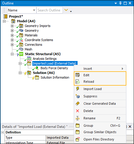
Note:If you have already selected a file and displayed the dialog, there are two additional context (right-click) menu options: and . The option re-opens the External Data dialog enabling you to modify the imported object's details and the option reloads data from the source file(s).
Although similar to using an External Data system in Workbench, there are some differences. You should review the External Data section of the Workbench User's Guide as well as the External Data System section in the Mechanical User's Guide for a description of the feature and its requirements.
Additional dialog options include:
Save Files with Project: Copy the external data files to the project directory. If left unchecked, the application references the source files directly using the File Path without making a copy. The default is unchecked.
Identifier: The identifier is a string that can be used to identify the file in the downstream Mechanical application.
Master: Specify the file as the master external data file. The nodal coordinate data for the selected master file is processed by the mapping utility. The application skips this nodal coordinate data in all other files. Only one file can be set as the master file. Mechanical APDL format type files should always be marked as the master file.
Note: For the H5DPF file format:
The Master option is selected by default and cannot be modified. This means that the nodal coordinate data will always be fetched from the currently selected file.
Only supports the use of one file in the dialog and cannot be duplicated.
Select the Browse button. The External Data Details dialog displays. It includes two tabs: Definition and Preview. See the Definition and Preview Tabs topic below for a description of these dialogs and their options.
Select the File Name option to navigate to and select your file. Specify dialog properties as needed and select OK.
Select the Import button. The data file is now associated with the object.
Definition and Preview Tabs
Descriptions of the properties of the Definition and Preview tabs for External Data Details dialog are shown below.
- Definition Tab
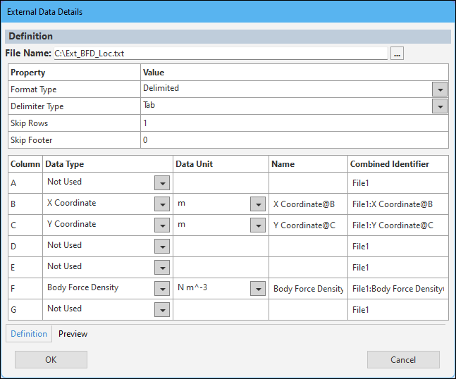
The Definition tab specifies the details of the external data file.
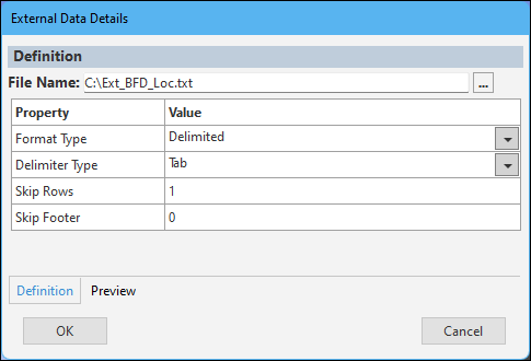
Properties for the Definition dialog include:
Property Description/Value Format Type
This property sets the corresponding format for the selected file. Different format types result in different properties. Options for this property include:
(default): Import a file containing data with each column delimited by a specific character. When selected, the Delimiter Type property also displays. This property specifies the delimiter used to separate the columns in data file. Options include , , , , and . If you select , the additional property User Defined Separator displays. You use this property to specify any character as the data delimiter.
Fixed Width[a]: This format type represents a file containing data in columns with a fixed width. Based on the width, the column specifies a string using Fortran-like fixed-format specifications. This is equivalent to the User-Defined option of the Format Type property as described in the External Data section of the Workbench User's Guide. Review the description in that section for the supported format specifiers, such as Decimal floating point, Scientific notation, etc.
MAPDL: Import a Mechanical APDL CDB data file. When selected, the following additional properties display:
Dimension: Specifies the source data dimension. Options include and (default).
Unit Lengths: Specifies the length unit used for source point locations. The default value is Meters.
Note: If you have multiple external data files that include the MAPDL import format, the property Average Corner Nodes To Midside Nodes displays under the Delimited or Fixed Width file definition. If you set this property to Yes, the application calculates data at the midside nodes as an average of the values contained at the corner nodes.
: Import a file in Hierarchical Data Format (HDF) Version 5 (.hdf5/.h5) format. This file type is only supported for Imported Velocity. See the Create Hierarchical Data Format File with Velocity Results Using DPF section of the Scripting in Mechanical Guide for an example script that enables you to create a .hdf5/.h5 file using the DPF.
Note: When importing .h5 files generated using result files from external solvers, make sure that the source coordinate system aligns with the target coordinate system. If an offset/rotation exists, see the Rigid Transformation topic in the Data Transfer Mesh Mapping section for the steps to apply the required transformations.
Skip Rows
Specifies the number of rows to skip at the start of the data source. The default is
0.Skip Footer
Specifies the number of rows to skip at the end of the data source. The default is
0.[a] Fixed Width Example
In the following example, the line has one integer followed by four exponential data types:
385 8.333333333E-003 9.375000000E-003 3.375000000E-001 0.000000000E+000
The corresponding format is 1i3,4e17.9.
Where:
The first entry is the number of occurrences.
The second entry is the format specifier.
The third entry is the number of characters of data in the definition (including numeric values (0-9), the letter “e” (for instances of scientific notation), and any white space and + or - signs).
The fourth entry is the number of digits after the decimal point.
Column Definition
When you select the or format types, the following table displays in the dialog.
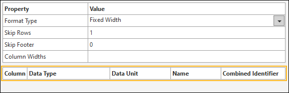
Column: Index field.
Data Type: Select a desired data type from the drop-down menu.
Name: String used to identify a specific column.
Combined Identifier: String that combines the File Identifier and Column names. It can be used to identify the column in the child imported load object.
- Preview Tab
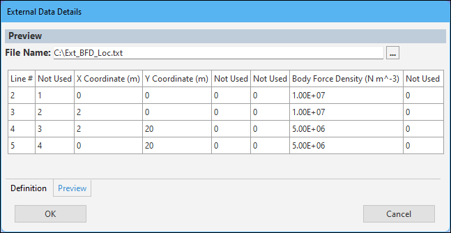
The Preview tab displays a preview of the imported lines from the file.
Note:The application only displays the first 10 rows of data for preview.
The Line # column refers to the line number in the source data file.