


This section describes the steps to create an Edge Crack. You can define this crack type on any face of a solid in order to cut into the face of the solid body.
Procedure
To define an Edge Crack:
Select the Model object.
Insert a Fracture object by right-clicking on the Model object and selecting Insert > Fracture. You can also select the Fracture option from the Define group on the Model Context Tab.
Note: Only one Fracture object is valid per Model.
Insert a Edge Crack object by right-clicking on the Fracture object and selecting Insert > Edge Crack. You can also select the Edge Crack option from the Crack group of the Fracture Context Tab.
A edge crack definition must always be scoped to a single solid body. Use the Body selection filter to pick a body in the Geometry window, click the Geometry field in the Details, and then click Apply.
Specify the properties of the crack. As you specify property values, the entries are reflected on the model in the Geometry window. Example entries are illustrated below.
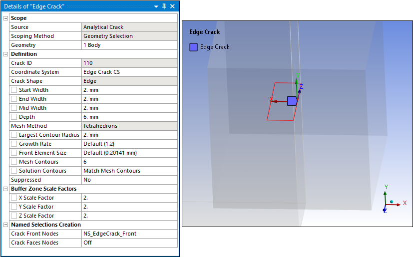
Crack categories and properties include:
- Definition
Crack ID: A read-only property that displays a unique system generated identification value. The application uses this identifier when creating solution identifiers for fracture parameters.
Coordinate System: Specify the coordinate system that defines the orientation of the crack. The Y axis of the specified coordinate system must be directed towards the normal of the crack plane and the crack plane always lies in the X-Z plane of the specified coordinate system.
Crack Shape: Read-only property set to .
Start Width: Specifies the width at the start of the crack. Enter a value greater than
0.End Width: Specifies the width at the end of the crack. Enter a value greater than
0.Mid Width: Specifies the width at the centre of the start and end of the crack. Enter a value greater than
0.Depth: Specifies the depth of the crack. Enter a value greater than
0.Mesh Method: This is a read-only property set to , the only supported method.
Largest Contour Radius: Specifies the largest contour radius for the crack shape. Enter a value greater than
0.Growth Rate: This property specifies the factor with which the mesh layers will grow along the radius of the crack. Specify a value greater than
1. The default value is1.2. The recommended value is equal to or greater than1.1.Front Element Size: This property specifies the element size for the crack front. The default value is computed using crack length. Specify a value greater than
0.Mesh Contours: Specifies the number of mesh contours for the crack shape. The value you enter must be equal to or greater than 1. The default setting is
6.Note: The maximum number of mesh contours the Geometry window can display is 100. However, you can specify a higher value and the application will process it accordingly.
Solution Contours: Specifies the number of mesh contours for which you want to compute the fracture result parameters. The value you enter must be less than or equal to the value of Mesh Contours, and cannot be greater than 99. By default, the value is Match Mesh Contours, indicating the number of Solution Contours is equal to the number of Mesh Contours. Entering 0 resets the value to Match Mesh Contours.
Suppressed: Toggles suppression of the crack object. The default is No. The application automatically suppresses the crack object if the scoped body becomes suppressed.
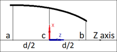
Note the following example that illustrates the Edge Crack geometric inputs, where a = Start Width, b = End Width, c = Mid Width, and d = the Depth of the crack.
- Buffer Zone Scale Factors
This category includes the following properties:
X Scale Factor
Y Scale Factor
Z Scale Factor
These properties control the size of the buffer zone in the X, Y, and Z directions, relative to the dimensions of the crack. For each scaling parameter, use the slider to set a value from
2to50. The default is2. The maximum dimension among the three directions of the crack is multiplied by the corresponding scale factors to create a buffer zone.- Named Selection Creation
The Named Selection Creation category of the Details displays Named Selections automatically created by the application following fracture mesh generation (Step 6 below). To ensure the Named Selections accurately correspond to the Edge Crack object, the application uses the following naming convention:
NS_EdgeCrack_Front
NS_EdgeCrack_TopFace
NS_EdgeCrack_BottomFace
For example, for a Edge Crack object named Edge Crack 4, the default names are NS_EdgeCrack 4_Front, NS_EdgeCrack 4_TopFace, and NS_EdgeCrack 4_BottomFace.
The properties of this category are defined as follows:
Crack Front Nodes: Identifies the Named Selection that is created automatically for the crack front (NS_EdgeCrack_Front). Contains nodes used for postprocessing of results.
Crack Faces Nodes: Determines whether Named Selections are created automatically for the crack’s top face and bottom face. These faces are both located in the XZ plane and are discontinuous. Options include and (default). If set to On, the following additional properties appear:
Top Face Nodes: Identifies the Named Selection that is created automatically for the top face (NS_EdgeCrack_TopFace). This face is discontinuity plane 1. It contains nodes used for applying a pressure to the top face. Bottom Face Nodes: Identifies the Named Selection that is created automatically for the bottom face (NS_EdgeCrack_BottomFace). This face is discontinuity plane 2. It contains nodes used for applying a pressure to the bottom face.
Select the Fracture object or Edge Crack object, right-click, and select Generate All Crack Meshes.
When the fracture mesh is generated, the requested Named Selections are automatically inserted into the Outline under the Edge Crack object with which they are associated.
Select the Show Mesh option on the Graphics Toolbar to display the fracture mesh.